
A3 Mk2
 Note
Note |
|
|

| Special tools and workshop equipment required |
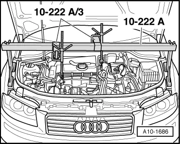
| t | Support bracket -10 - 222 A- |
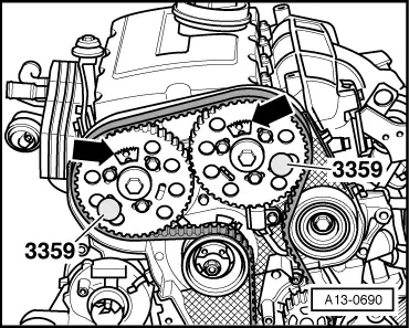
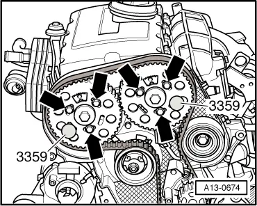
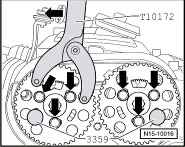
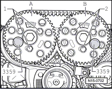
| t | Diesel injection pump locking pin -3359- (2x) |
| t | Spring type clip pliers -VAS 5024 A- |
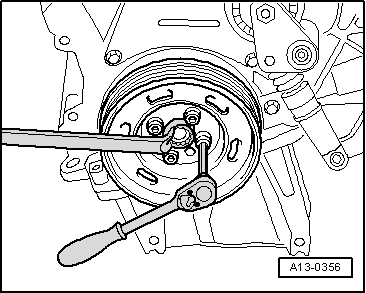
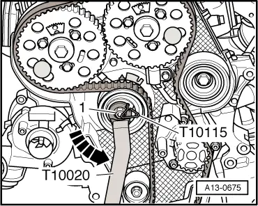
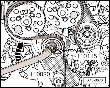
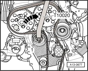
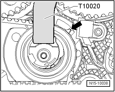
| t | Pin wrench -T10020- |
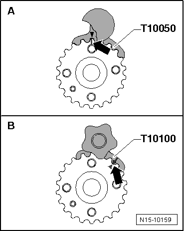
| t | Crankshaft stop -T10050- for engines with circular crankshaft sprocket |
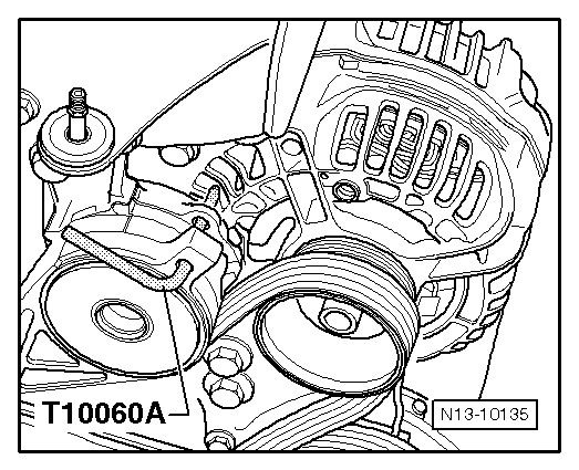
| t | Locking pin -T10060 A- |

| t | Crankshaft stop -T10100- for engines with oval crankshaft sprocket |
| t | Locking pin -T10115- |
| t | Counterhold tool -T10172- |
| t | Locking fluid → Electronic parts catalogue |
| t | Safety goggles |
| t | Protective gloves |
|
|
|
|
|
|
 Caution
 WARNING
|
|
|
|
|
|
Note |
|
|
|
|
|
|
|
|
|
|
|
|
|
|
|
Note
|
|
|
|
|
|
|
|
|
|
|
|
|
|
|
|
|
|
|
|
|
|
Note
|
|
Note
|
|
Note
|
|
|
|
|
|
|
|
|
|
Note
Note |
|
|
|
|
|
|
|
|
|
Note
|
|
Note
|
|
| Component | Nm | ||||||||
| Tensioning roller for toothed belt to cylinder head | 20 + 45° 1) | ||||||||
| Camshaft sprocket to hub | 25 | ||||||||
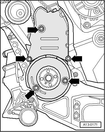
| Toothed belt cover (bottom) to cylinder block | 10 2) | ||||||||
| Toothed belt cover (centre) to cylinder block | 10 2) | ||||||||
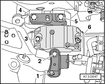
| Engine mounting to body | 50 | ||||||||
| Connecting bracket to engine mounting/body | 20 + 90° 3)4) | ||||||||
| Pendulum support to subframe | Manual gearbox → Rep. Gr.34, automatic gearbox → Rep. Gr.37 | ||||||||
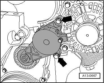
| Tensioner for poly V-belt to bracket for ancillaries | 23 | ||||||||
| |||||||||