audi Workshop Repair Guides

Audi Workshop Service and Repair Manuals

Removing and installing parts of ABS system on front axle > < Anti-lock brake system (ABS) Bosch 8.0
ABS Bosch 8.0
ABS Bosch 8.0
The following configurations are possible on vehicles with the ABS Bosch 8.0 system:
t  ABS/EDL/TCS/ESP
The vehicle is equipped with a diagonally split ABS brake system. The servo-assistance is pneumatic, supplied by the vacuum brake servo unit.
Malfunctions in the ABS system do not influence the brake system and servo. The conventional braking system remains functional even without ABS. A change in braking behaviour must be reckoned with. After the ABS warning lamp comes on, the rear wheels can lock early when braking!
The direct connection between these components reduces possible sources of faults. There is no provision for repairing the hydraulic control unit - it must be renewed if necessary.
   
Bosch 8.0 ABS/EDL/TCS/ESP:
Removing and installing control unit and hydraulic unit
→ Chapter
Hydraulic unit and brake lines
  N45-10069
1 - Brake master cylinder and brake servo
2 - Brake line
q   Brake master cylinder/primary piston circuit to hydraulic unit
3 - Brake line
q   Brake master cylinder/secondary piston circuit to hydraulic unit
4 - Brake line
q   Hydraulic unit to front right brake caliper
5 - Brake line
q   Hydraulic unit to rear left brake caliper
6 - Brake line
q   Hydraulic unit to rear right brake caliper
7 - Brake line
q   Hydraulic unit to front left brake caliper
8 - ABS hydraulic unit -N55- with ABS control unit with EDL -J104-
q   With integrated brake pressure sender
q   Removing and installing → Chapter
9 - Buffer (2 x)
10 - Longitudinal member (body)
11 - Nut and washer assembly, 10 Nm
12 - Bracket for ESP
13 - Bolt with bonded rubber bush, tightening torque 10 Nm
q   Cannot be removed from component
14 - Nut and washer assembly, 8 Nm
15 - Washer

Removing and installing hydraulic control unit
Special tools and workshop equipment required
   
t  Torque wrench -V.A.G 1331-
t  Brake pedal actuator -V.A.G 1869/2-
  W00-0427
t  Sealing plugs (repair kit) -1H0 698 311 A-
Removing
Fitting location:
  W00-0679
The hydraulic control unit is fitted on the left-hand side of the engine compartment.
  WARNING
Do not bend the brake lines.
–  Note or request radio code on vehicles with coded radio if necessary.
–  Disconnect battery → Rep. Gr.27
  A45-10007
–  Detach plenum chamber cover.
  A45-10003
–  Remove hexagon bolts -1- securing coolant expansion tank.
–  Unplug connector from coolant expansion tank.
  A45-10015
–  Move coolant expansion tank clear to one side.
  A45-10014
–  Insert brake pedal actuator -V.A.G 1869/2- between brake pedal and driver's seat. Depress the brake pedal at least 60 mm.
–  Connect hose of bleeder bottle to bleeder screws of front left and rear left brake calipers and open bleeder screws.
  Note
This will release the pressure in the hydraulic unit.
–  Close front left and rear left bleeder screws.
–  Do not remove brake pedal actuator -V.A.G 1869/2-.
–  As protection against escaping brake fluid, place a sufficient number of lint-free cloths in area beneath control unit and hydraulic unit.
  Note
Mark brake lines with numbers.
  WARNING
Do not bend the brake lines in the vicinity of the hydraulic unit.
  A44-0020
–  Disconnect brake lines between hydraulic unit and brake master cylinder completely.
–  Disconnect remaining brake lines -arrows- on hydraulic unit.
–  Seal brake pipes and tapped holes with sealing plugs from repair kit.
  A45-10016
–  Open brake line retainer -1- .
  A45-10038
–  Press red locking slide upwards.
  Note
t  Make sure brake fluid does not get into connector housing of control unit. This can result in corrosion of the contacts and failure of the system.
t  Use compressed air to carefully clean connector housing if necessary.
–  Release control unit connector -arrow- and unplug.
  A45-10016
–  Push retaining clip in -direction of arrow- and unplug connector.
  A45-10017
–  Remove hexagon bolts -1-.
–  Remove hydraulic control unit.
Installing
Installation is performed in reverse sequence; note the following:
  Note
t  Do not remove sealing plugs from new hydraulic unit until corresponding brake line is ready to be fitted.
t  If sealing plugs are removed from hydraulic unit sooner, brake fluid may escape and it may no longer be possible to fill and bleed the unit properly.
  A45-10018
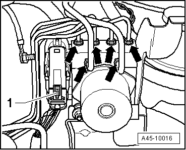
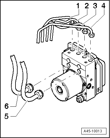
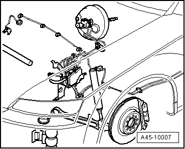
–  Connect pipes as previously marked:
1 - To front right brake caliper
2 - To rear left brake caliper
3 - To rear right brake caliper
4 - To front left brake caliper
5 - To primary piston circuit
6 - To secondary piston circuit
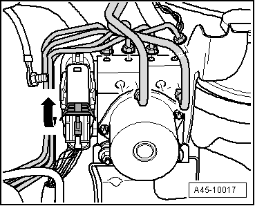
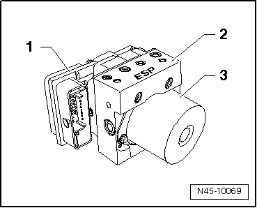
–  Fit connector on hydraulic pump.
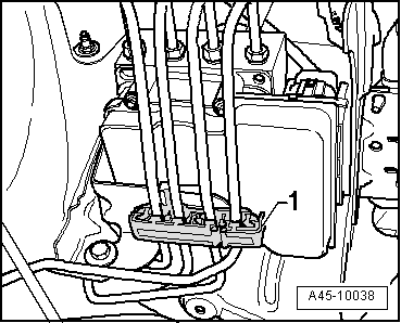
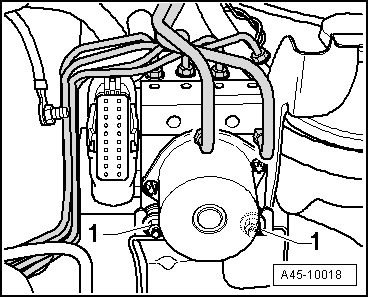
–  Clip ABS unit onto bracket.
  Note
Do not tighten bolts completely. This will make it easier to attach the individual brake lines to the hydraulic unit.
–  After tightening brake lines, tighten hydraulic unit.
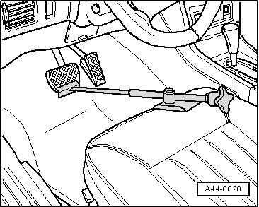
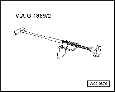
–  Remove brake pedal actuator -V.A.G 1869/2-.
–  Bleed brake system → Chapter.
–  Code ABS with EDL control unit -J104-. → Code control unit using VAS 5051 via "Guided Fault Finding" function.
–  When renewing the control unit, select the function “Replacing” for the relevant control unit in the “Guided Fault Finding”.
To do so, use the vehicle diagnosis, testing and information system -VAS 5051A-.
–  Perform final control diagnosis after attaching brake lines to hydraulic unit. → Vehicle diagnostic, testing and information systemVAS 5051A
  Note
Final control diagnosis can be used to establish whether line connections have been interchanged → Chapter.
Tightening torques
  A45-10013
Component Nm
Brake lines to hydraulic unit M10 (brake line diameter 5 mm)12
Brake lines to hydraulic unit M12 (brake line diameter 5 mm)12
Brake lines to hydraulic unit M12 (brake line diameter 8 mm)16


Removing and installing parts of ABS system on front axle > < Anti-lock brake system (ABS) Bosch 8.0