audi Workshop Repair Guides

Audi Workshop Service and Repair Manuals

Installing gearbox > < Removing gearbox - vehicles with V6 petrol engine
Removing gearbox - vehicles with V6 TDI engine
   
Removing gearbox - vehicles with V6 TDI engine
Special tools and workshop equipment required
t  Support bracket -10-222 A-
t  Gearbox support -3282-
t  Adjustment plate -3282/12-
t  Engine and gearbox jack -V.A.G 1383 A-

   
t  Counterhold tool -T10172- with adapter -T10172/5-
  W00-1386
t  Used oil collection and extraction unit -V.A.G 1782-
  W00-10211
t  Wing compensation plates -T40045-
  W00-1401
Procedure
  Caution
Follow steps required when disconnecting battery → Rep. Gr.27.
–  Detach rubber seal of plenum chamber cover in direction of -arrow-.
–  Detach plenum chamber cover -1- to front.
–  With ignition switched off, disconnect earth wire at battery → Rep. Gr.27.
  A27-0088
–  Remove engine cover panel -arrows-.
  A10-0202
–  Pull off bonnet seal at both wing mounting flanges.
–  To avoid damaging edges of wing panels with support bracket -10-222 A-, insert wing compensation plates -T40045- on both sides between the wing mounting flange and the body panel underneath.
  A19-0412
–  Set up support bracket -10-222 A- with racks -10-222 A/1-.
–  Take up some of the engine weight by tightening spindle of support bracket, but do not lift.
  A34-0449
–  On vehicles fitted with auxiliary heater, remove screws -arrows- securing exhaust pipe of auxiliary/ additional heater to noise insulation.
  A10-0407
–  Release fasteners -1 ... 3- and detach noise insulation panels (front -A- and rear -B-).
  A34-0530
–  Detach bracket -arrow- for noise insulation.
  N34-0588
–  Unscrew bolts -1 ... 4- and remove front cross piece, if fitted.
  A26-0568
–  Unscrew nuts -1- at connection between starter catalytic converter and front exhaust pipe with catalytic converters.
  A26-0362
–  Release clamps -1- and remove front exhaust pipe with catalytic converters -2-.
  A34-0450
–  Unbolt heat shield for left-side drive shaft -arrows-.
–  Remove drive shafts -1- (left and right) from gearbox flange shafts and tie up to side as far as possible.
  Note
Make sure you do not damage surface coating on drive shafts.
  A34-0138
–  Unbolt heat shield for propshaft -arrows-.
  V39-1844
–  Unbolt propshaft from gearbox.
–  To do this, use counterhold tool -T10172- with adapter -T10172/5-
  A39-10185
–  Use wire -arrow- to tie up propshaft -1- onto heat shield.
  A34-0447
–  Apply lifting column of engine and gearbox jack -V.A.G 1383 A- to gearbox from below (place a block of wood -arrow- between lifting column and gearbox) and support gearbox.
  A34-0495
–  First remove bolts -1- and then bolts -2- at rear cross member.
–  Unscrew two nuts -3- and detach rear cross member.
  A34-0451
–  Use engine and gearbox jack -V.A.G 1383 A- to lift gearbox up slightly.
  A34-0495
–  Unscrew bottom engine/gearbox securing bolts -arrows-.
–  Lower gearbox again.
  A34-0433
–  Unplug electrical connector -arrow- for reversing light switch -F4- on gearbox (right-side).
–  Move electrical wiring clear.
  A34-0497
–  If fitted, unplug electrical connector -arrow- for speedometer sender -G22- on left of gearbox.
  A34-0498
–  If fitted, unbolt head shield for engine speed sender -G28- from gearbox and remove bolt -arrow-.
–  Remove engine speed sender -G28- and move clear.
  A34-0119
–  Unscrew connecting rod -2- for selector rod.
–  Detach push rod -1-; to do so, unscrew hexagon socket head bolt.
  N34-1208
–  Unscrew nut -1- and detach selector shaft lever -2- from gearbox selector shaft.
  A34-0140
–  Unbolt starter and secure to side of engine compartment if necessary → Rep. Gr.27.
  Note
Starter cables do not have to be disconnected.
–  Disconnect all other electrical connections and earth wires from gearbox and from the engine/gearbox securing bolts.
  N34-0589
–  Place used oil collection and extraction unit -V.A.G 1782- below gearbox.
–  Remove gear oil pipes -arrows- and seal openings with plugs.
–  Disconnect gear oil pipes at connection point in front of drive shaft (right-side)
–  Unscrew bottom engine/gearbox securing bolts.
  A34-0086
–  To remove manual gearbox 01E (four-wheel drive) set up gearbox support -3282- with adjustment plate -3282/12- and place on engine and gearbox jack -V.A.G 1383 A-.
–  Fit support elements -A-.
  Note
  V34-2930
t  The positions of the support elements are shown on the adjustment plate -3282/12- in schematic form -A- (the arrow -B- points in direction of travel).
t  The adjustment plate can only be fitted in one position.
  V34-2931
–  Place engine and gearbox jack -1383 A- with gearbox support -3282- underneath gearbox and position adjustment plate so it is parallel with gearbox.
  N34-1206
–  Secure support elements -arrow- to left and right side of gearbox.
  N34-1207
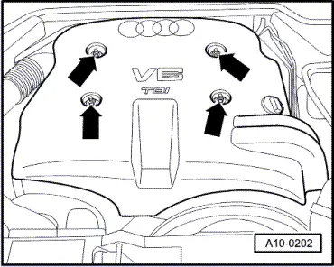
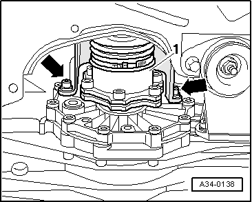
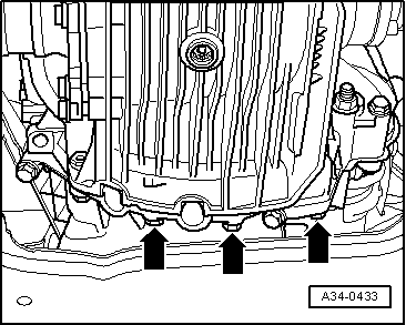
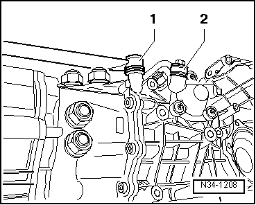
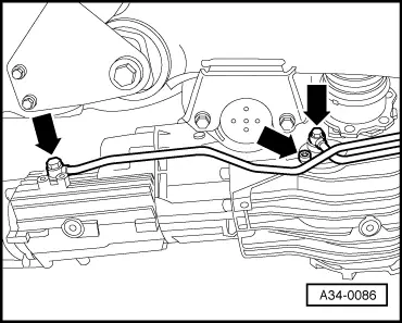
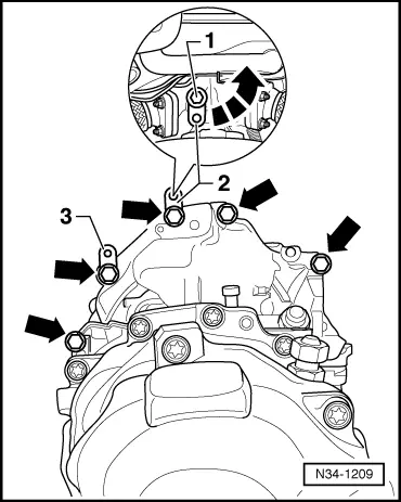
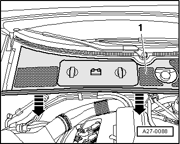
–  Unscrew top engine/gearbox securing bolts -arrows-.
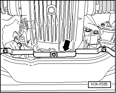
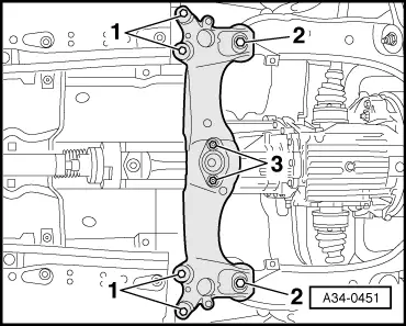
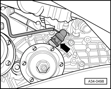
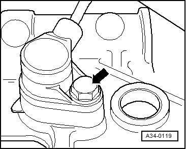
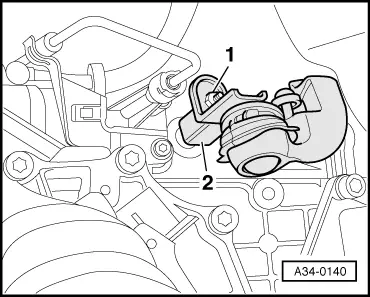
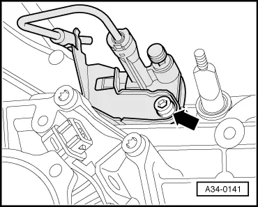
–  Slacken bolt -1- (at rear of turbocharger) a few turns and pivot brace -2- to one side in direction of -arrow-. Then tighten bolt -1- again lightly.
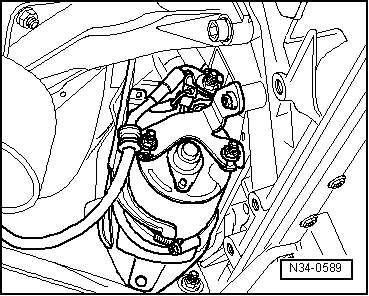
–  If fitted, move bracket -3- with wiring clear to the side and secure with wire.
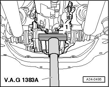
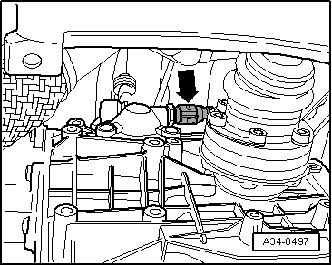
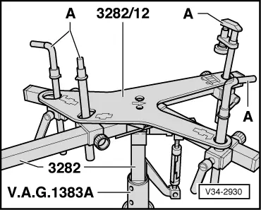
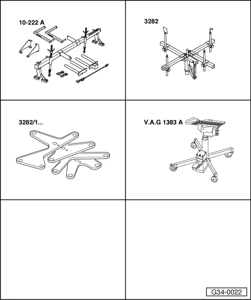
–  Press gearbox off dowel sleeves and lower carefully with engine and gearbox jack -V.A.G 1383 A- just far enough to gain access to the clutch slave cylinder.
  Note
When lowering gearbox, ensure hydraulic pipe/hose to slave cylinder is not damaged.
  N34-1209
–  Remove clutch slave cylinder -arrow- and tie up with wire. Do not disconnect hoses/pipes.
  Caution
t  Do not depress clutch pedal after removing clutch slave cylinder.
t  The slave cylinder would then be destroyed once pedal force exceeds approx. 300 N.
–  Lower gearbox completely with engine and gearbox jack -V.A.G 1383 A-.
  Note
t  Make sure that all wiring has been detached from top of gearbox.
t  When lowering gearbox, make sure there is sufficient clearance from drive shafts.
  A34-0141
–  If the removed gearbox is being renewed, the gearbox mounting -1- must be transferred to the replacement gearbox -bolts 2-.
  A34-10008

Installing gearbox > < Removing gearbox - vehicles with V6 petrol engine