
A4 Cabriolet Mk2
| Removing and installing 1st, 2nd and reverse gear - exploded view |
 Note
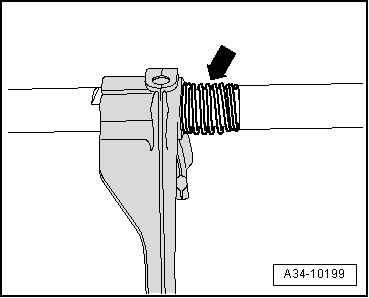
Note| t | Items 8 and 11 to 18 were modified on 1st and 2nd gear selector rod version with spring-loaded selector fork → Fig.. Refer to → Electronic parts catalogue “(ETKA)” to allocate components. |
| t | Selector gears should have an axial play of min. 0.10 mm after installing. |
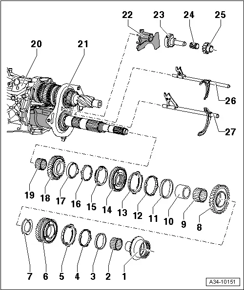
| 1 - | Clutch unit |
| q | Removing and installing → Chapter |
| 2 - | Needle bearing |
| q | For reverse selector gear |
| 3 - | Inner ring for reverse gear |
| q | Installation position → Fig. |
| q | Renew if scored or if there are visible traces of wear |
| 4 - | Intermediate ring for reverse gear |
| q | Installation position → Fig. |
| q | Checking for wear → Fig. |
| 5 - | Synchro-ring for reverse gear |
| q | Installation position → Fig. |
| q | Checking for wear → Fig. |
| q | Renew if scored or if there are visible traces of wear |
| 6 - | Reverse selector gear |
| q | With locking collar for reverse gear |
| q | Assembling locking collar and reverse selector gear → Fig. |
| 7 - | Thrust washer |
| q | For 1st speed selector gear and reverse gear |
| 8 - | 1st speed selector gear |
| 9 - | Needle bearing |
| q | For 1st gear |
| 10 - | Needle bearing inner race |
| q | For 1st speed selector gear |
| 11 - | Inner ring for 1st gear |
| q | Installation position → Fig. |
| q | Checking for wear → Fig. |
| q | Renew if scored or if there are visible traces of wear |
| 12 - | Intermediate ring for 1st gear |
| q | Installation position → Fig. |
| q | Checking for wear → Fig. |
| 13 - | Synchro-ring for 1st gear |
| q | Installation position → Fig. |
| q | Checking for wear → Fig. |
| q | Renew if scored or if there are visible traces of wear |
| 14 - | Locking collar/synchronising hub for 1st and 2nd gear |
| q | Note correct installation position of locking collar → Fig. |
| q | Assembling locking collar/synchronising hub → Anchor |
| 15 - | Synchro-ring for 2nd gear |
| q | Installation position → Fig. |
| q | Checking for wear → Fig. |
| q | Renew if scored or if there are visible traces of wear |
| 16 - | Intermediate ring for 2nd gear |
| q | Installation position → Fig. |
| q | Checking for wear → Fig. |
| 17 - | Inner ring for 2nd gear |
| q | Installation position → Fig. |
| q | Checking for wear → Fig. |
| q | Renew if scored or if there are visible traces of wear |
| 18 - | 2nd speed selector gear |
| 19 - | Needle bearing |
| q | For 2nd gear |
| 20 - | Gearbox housing |
| q | Removing and installing input shaft, hollow shaft and pinion shaft → Chapter |
| 21 - | Bearing mounting |
| q | Supports bearings for input shaft and hollow shaft in gearbox cover |
| 22 - | Mounting for reverse shaft |
| q | Clip into bearing mounting → Item |
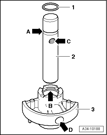
| 23 - | Reverse shaft |
| q | With support for reverse shaft |
| q | Assembling reverse shaft and support for reverse shaft → Fig. |
| 24 - | Needle bearing |
| q | For reverse gear wheel |
| 25 - | Reverse gear wheel |
| q | Installation position: teeth face mounting for reverse shaft |
| 26 - | Selector rod for 1st and 2nd gear |
| q | Installation position → Fig. |
| q | Only to be renewed complete with pinned selector fork for 1st and 2nd gear |
| q | Modification: with spring-loaded selector fork → Fig., allocate via → Electronic parts catalogue “ETKA”. |
| 27 - | Reverse gear selector rod |
| q | Installation position → Fig. |
| q | Only to be renewed complete with pinned selector fork for reverse gear |
|
|