audi Workshop Repair Guides

Audi Workshop Service and Repair Manuals

Removing and installing camshaft control valve 1 N205 > < Removing and installing cylinder head
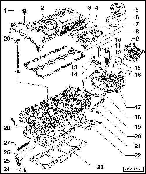
Cylinder head - exploded view
  Note
t  Renew the cylinder head bolts.
t  On assembly, renew oil seals and gaskets as well as self-locking nuts and bolts that are tightened by turning through to a specified angle.
t  When installing an exchange cylinder head with fitted camshafts, oil the contact surfaces between the roller rocker fingers and cams.
t  The plastic protectors fitted to protect the open valves must only be removed immediately before fitting the cylinder head.
t  When fitting a new cylinder head or cylinder head gasket, drain off all the old coolant and refill with new coolant.
   
1 - Bolt
q   Tightening sequence → Fig.
2 - Cylinder head cover
q   Removing and installing → Chapter
3 - Gasket
q   Renew if damaged or leaking
4 - Valve housing
5 - Oil filler cap
6 - Seal
q   Renew if damaged or leaking
7 - 4 Nm
8 - Gasket for cylinder head cover
q   Renew if damaged or leaking
9 - Exhauster pump
10 - 4 Nm
11 - Camshaft control valve 1 -N205-
q   Removing → Chapter
12 - Seal
q   Renew
13 - 10 Nm
14 - Cable retainer
15 - Seal
q   Renew if damaged or leaking
16 - 10 Nm
17 - Housing
18 - Gasket
q   Renew
19 - Transport plate
20 - 25 Nm
21 - 10 Nm
q   Stud for intake manifold
22 - Separating plate
23 - Cylinder head gasket
q   Renew
q   Check installation position: Part No. towards cylinder head
24 - 10 Nm
25 - Hall sender -G40-
26 - Seal
27 - 10 Nm
q   Stud for tensioning roller
28 - 20 Nm
q   Stud for exhaust manifold
29 - Cylinder head bolt
q   Renew
q   Note correct sequence when loosening → Anchor
q   Tightening torque → Fig.

   
Tightening sequence for cylinder head cover
–  Tighten bolts to 10 Nm in the sequence indicated.
  N15-10047
Tightening sequence for cylinder head
–  Tighten using torque wrench:
t  1st stage: 40 Nm
–  Tighten using rigid spanner:
t  2nd stage: turn 180° (1/2 turn) further (alternatively 2 x 90° is possible)
  A15-0767
Checking cylinder head for distortion
–  Use straight edge and feeler gauge to measure for distortion at several points.
t  Max. permissible distortion: 0.05 mm
  V15-0654
Cylinder head machining limit
–  Machining of the cylinder head (surface grinding) is only permissible down to the minimum dimension -a-.
t  Minimum dimension -a- = 139.20 mm
  A15-0169

Removing and installing camshaft control valve 1 N205 > < Removing and installing cylinder head