
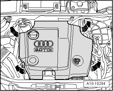
A4 Cabriolet Mk2
| Removing and installing camshafts |

| Special tools and workshop equipment required |
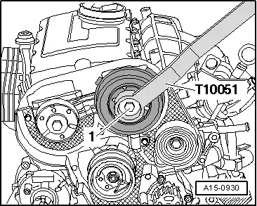
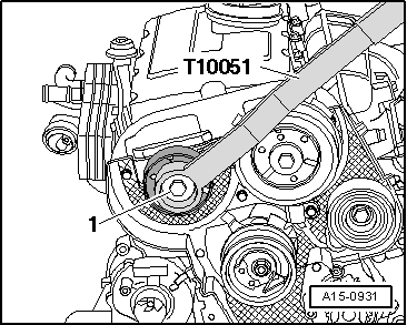
| t | Counterhold tool -T10051- |
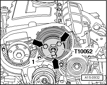
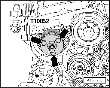
| t | Puller -T10052- |
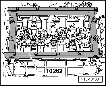
| t | Rack -T10262- |
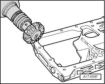
| t | Electric drill with plastic brush attachment |
| t | Safety goggles |
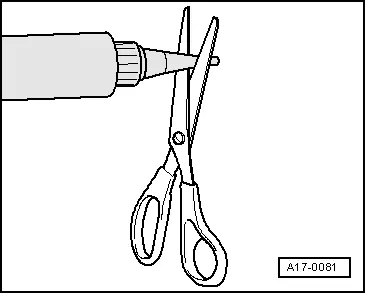
| t | Sealant → Electronic parts catalogue |
|
|
 Note
Note
|
|
|
|
|
|
|
|
|
|
|
|
|
|
|
|
Note
|
|
|
|
|
|
Note
Note
|
|
|
|
|
|
 Caution
|

|
Note
|
|
Note
Note
|
|
 WARNING
|
|
|
|
Note
|
|
|
|
Note
|
|
| Component | Nm | ||||||
| Bearing frame to cylinder head | 20 | ||||||
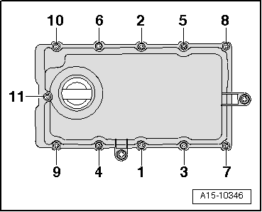
| Rocker arm shaft to cylinder head | 20 + 90° 1)2) | ||||||
| Toothed belt cover (rear) to bearing frame | 10 3) | ||||||
| Bracket for exhaust gas recirculation cooler to cylinder head | 10 | ||||||
| Stop for torque reaction support to lock carrier | 28 | ||||||
| Hose clips (9 mm wide) | 3 | ||||||
| Hose clips (13 mm wide) | 5.5 | ||||||
| |||||||