
A4 Cabriolet Mk2
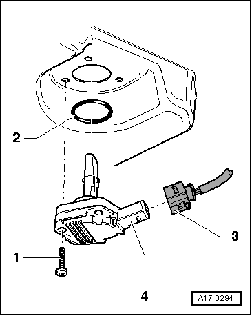
| Sump, oil pump - exploded view of components |

| 1 - | 10 Nm |
| q | Tighten in stages and in diagonal sequence |
| 2 - | Sump (bottom section) |
| q | Removing and installing → Chapter |
| q | With oil level/oil temperature sender -G266- |
| q | Removing and installing the oil level/temperature sender -G266- → Fig. |
| 3 - | Chain guard |
| 4 - | 10 Nm |
| 5 - | 22 Nm |
| 6 - | Oil pump |
| q | With pressure control valve: 3.8 bar |
| q | With pressure relief valve (11 bar) |
| q | Removing and installing → Chapter |
| 7 - | Drive chain for oil pump |
| q | Removing and installing → Chapter |
| 8 - | Chain sprocket for oil pump |
| 9 - | 22 Nm |
| 10 - | O-ring |
| q | Inserted in front sealing flange |
| q | Renew |
| 11 - | 10 Nm |
| 12 - | Banjo bolt, 10 Nm |
| 13 - | Bolt |
| q | M6 to cylinder block = 13 Nm |
| q | M6 to sealing flange = 10 Nm |
| q | M7 = 16 Nm |
| q | For correct version refer to → Parts catalogue |
| 14 - | 40 Nm |
| 15 - | Torque reaction support |
| 16 - | O-ring |
| q | Renew |
| 17 - | Guide tube for oil dipstick |
| q | Tighten to 10 Nm |
| 18 - | Sump (top section) |
| q | Removing and installing → Chapter |
| 19 - | 45 Nm |
| 20 - | Oil pipe |
| q | From oil pump to balance shaft housing |
| 21 - | Banjo bolt, 10 Nm |
| 22 - | O-ring |
| q | Renew |
| 23 - | 10 Nm |
| 24 - | Oil pressure pipe |
| 25 - | 45 Nm |
| 26 - | Balance shaft housing |
| q | With balance shaft |
| q | Removing and installing → Chapter „Removing and installing sump (top section)“ |
| 27 - | 10 Nm |
| 28 - | 10 Nm |
| 29 - | Idler sprocket |
| 30 - | 22 Nm |
| 31 - | Baffle plate |
| 32 - | 10 Nm |
| 33 - | Oil drain plug, 25 Nm |
| 34 - | Seal |
| q | Renew |
|
|