
A4 Cabriolet Mk2
| Valve gear - exploded view |
 Note
Note| Illustration shows left-side cylinder head. |
| 1 - | 10 Nm |
| 2 - | Oil seals |
| q | Renewing → Chapter |
| 3 - | Housing |
| q | For camshaft control valves |
| 4 - | Gasket |
| q | Renew |
| 5 - | Exhaust camshaft |
| q | Removing and installing → Chapter |
| q | Checking axial clearance → Chapter |
| q | Check with Plastigage (bucket tappets removed) |
| q | Radial clearance: wear limit: 0.1 mm |
| q | Runout: max. 0.01 mm |
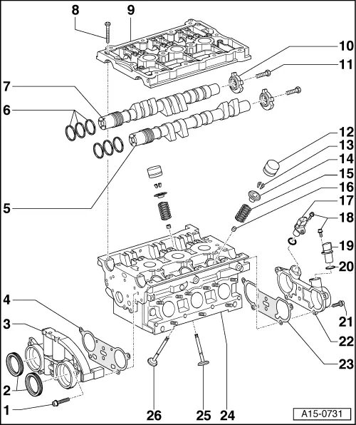
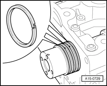
| 6 - | Compression rings for camshaft adjuster |
| q | Depending on version, some piston ring types are provided with lugs at the ends |
| q | Hook ends of compression rings together → Fig. |
| 7 - | Inlet camshaft |
| q | Removing and installing → Chapter |
| q | Checking axial clearance → Chapter |
| q | Check with Plastigage (bucket tappets removed) |
| q | Radial clearance: wear limit: 0.1 mm |
| q | Runout: max. 0.01 mm |
| 8 - | 10 Nm |
| q | Tighten in several stages, working from inside to outside |
| 9 - | Retaining frame |
| q | With integrated camshaft bearings |
| q | Removing and installing → Chapter „Removing and installing camshafts and camshaft adjuster“ |
| 10 - | Rotor for Hall sender |
| q | Note installation position (notch on camshaft) |
| 11 - | 23 Nm |
| 12 - | Hydraulic bucket tappet |
| q | Checking → Chapter |
| q | Removing and installing → Chapter „Renewing valve stem oil seals with cylinder head installed“ |
| q | Do not interchange |
| q | Place down with contact surface facing downwards |
| q | Check axial clearance of camshaft before installing → Chapter |
| q | Lubricate contact surface |
| 13 - | Valve cotters |
| 14 - | Valve spring plate |
| 15 - | Valve spring |
| 16 - | Valve stem oil seal |
| q | Renewing with cylinder head installed → Chapter |
| q | Renewing with cylinder head removed → Chapter |
| 17 - | Hall sender for inlet camshaft |
| q | Cylinder bank 1 (right-side): Hall sender -G40- |
| q | Cylinder bank 2 (left-side): Hall sender 2 -G163- |
| 18 - | 10 Nm |
| 19 - | Hall sender for exhaust camshaft |
| q | Cylinder bank 1 (right-side): Hall sender 3 -G300- |
| q | Cylinder bank 2 (left-side): Hall sender 4 -G301- |
| 20 - | O-ring |
| q | Renew |
| 21 - | 10 Nm |
| 22 - | Hall sender housing |
| 23 - | Gasket |
| q | Renew |
| 24 - | Cylinder head |
| q | See note → Chapter |
| q | Checking valve guides, grinding-in valve seats → Chapter |
| q | Machining valve seats → Chapter |
| 25 - | Inlet valve |
| q | Do not machine, only grinding-in is permitted |
| q | Mark installation position for re-installation |
| q | Valve dimensions → Chapter |
| q | Checking valve guides, grinding-in valve seats → Chapter |
| 26 - | Exhaust valve |
| q | Do not machine, only grinding-in is permitted |
| q | Mark installation position for re-installation |
| q | Valve dimensions → Chapter |
| q | Checking valve guides, grinding-in valve seats → Chapter |
|
|