A4 Mk1
|
Removing and installing differential
Removing and installing differential
Special tools, testers and auxiliary equipment required
Notes:
|
 |
|
|
|
|
|
|
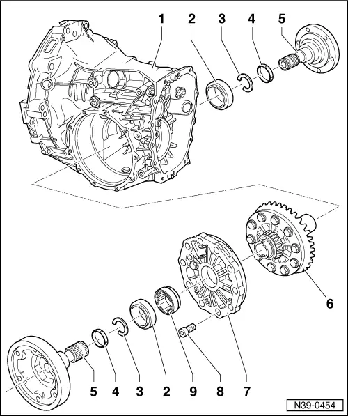
=> Parts List
|
|
|
|
 |
|
|
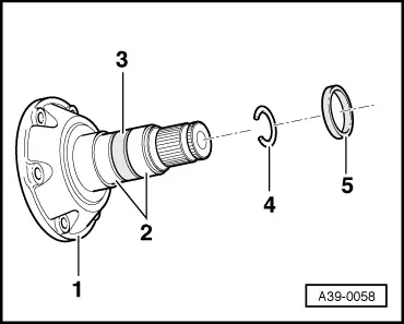
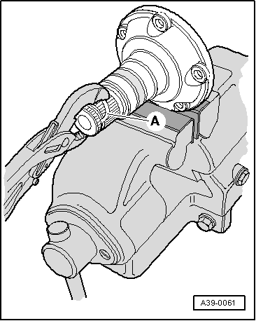
→ Fig.1 Removing and installing circlip
|
 |
|
|
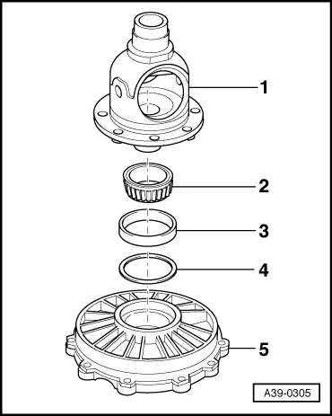
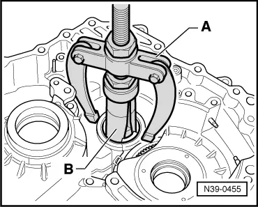
→ Fig.2 Removing spacer ring
|
 |
|
|
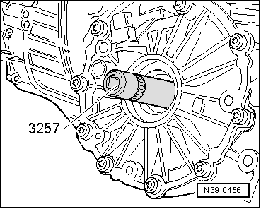
→ Fig.3 Installing spacer ring
|