
A4 Mk1
 |
|
|
Notes: |
|
|
|
|
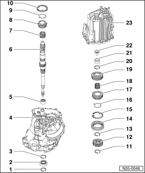
=> Parts List
|
|
|
|
|
|
=> Parts List |
|
|
|
 |
|
|
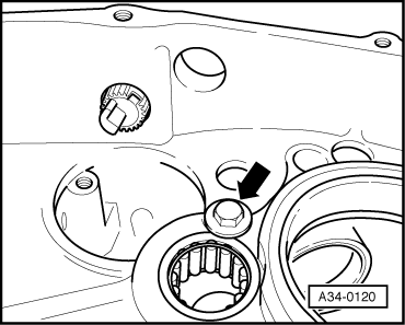
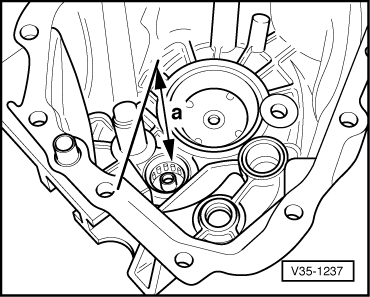
→ Fig.1 Unscrewing securing bolt -arrow- for needle roller bearing
Note: Bolt is not fitted on all versions. |
 |
|
|
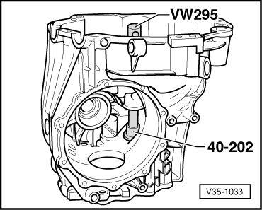
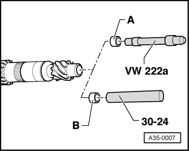
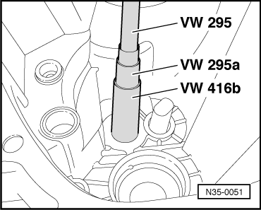
→ Fig.2 Driving out needle roller bearing |
 |
|
|
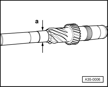
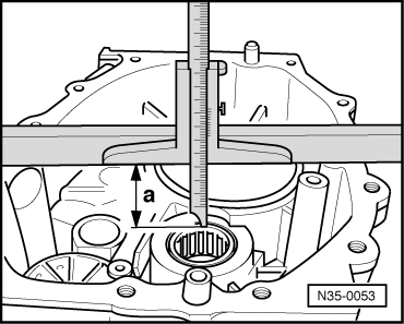
→ Fig.4 Installation position of needle roller bearing Distance -a- from lower edge of straight-edge to upper edge of needle roller bearing = 39.5 mm Note: Measure distance from top edge of straight-edge and subtract the width of the straight-edge from the measured distance. |
 |
|
|
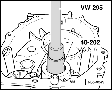
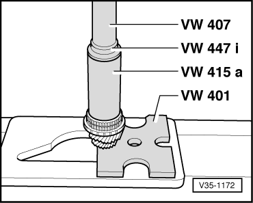
→ Fig.5 Pressing in needle roller bearing |
|
|
|
→ Fig.6 Screwing in securing bolt -arrow- Note: Bolt is not fitted on all versions.
|
 |
||||||||||
|
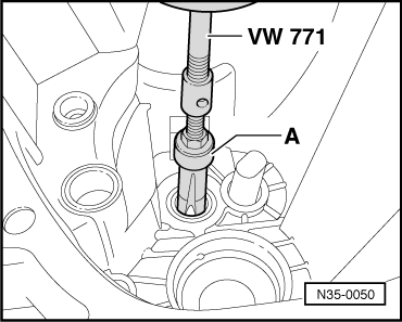
→ Fig.7 Knocking oil feed sleeve into input shaft
|
 |
|
|
→ Fig.8 Pulling out roller sleeve A - Internal puller, e. g. Kukko 21/4, 22 ... 28 mm
|
 |
|
|
→ Fig.9 Installation position of roller sleeve
|
 |
|
|
→ Fig.10 Driving in roller sleeve |
 |
|
|
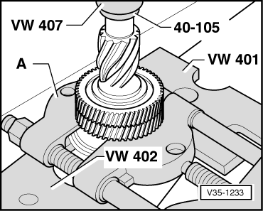
→ Fig.11 Pressing off 5th gear wheel
|
 |
|
|
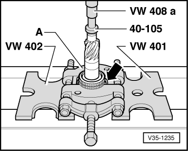
→ Fig.12 Pressing off synchro hub for 3rd and 4th gear
|
 |
|
|
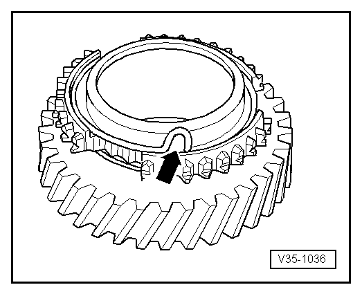
→ Fig.13 Inserting spring in sliding gear The bent end of the spring (arrow) must be hooked in the hole in the sliding gear. |
 |
|
|
→ Fig.14 Checking synchro-ring for wear
The calculated value must not be less than 0.5 mm. |
 |
|
|
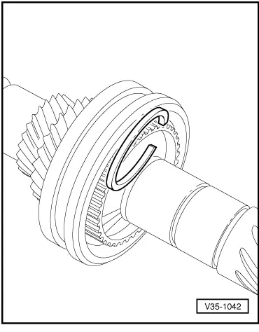
→ Fig.15 Installation position of circlips
|
 |
||||||||||||||||||||
|
→ Fig.16 Determining thickness of circlip
=> Parts List Available circlips for 3rd and 4th gear synchro-hubs
Available circlips for 5th gear wheel
| ||||||||||||||||||||
 |
|
|
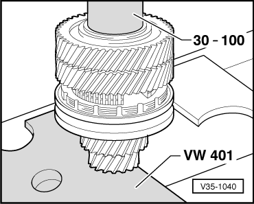
→ Fig.17 Pressing on synchro hub for 3rd and 4th gear
|
 |
|
|
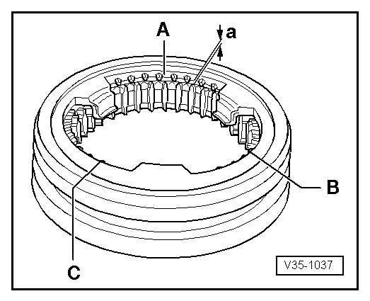
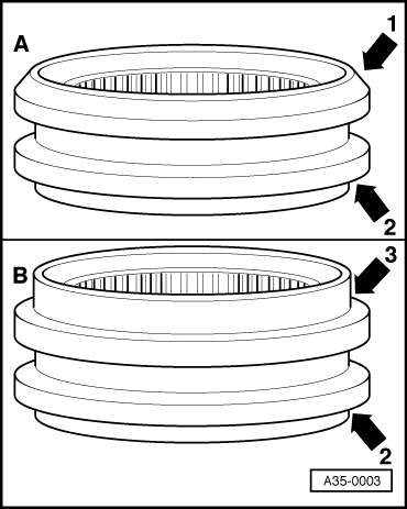
→ Fig.18 Installation position of locking collar Different types of locking collar are installed: version -A- with chamfered edge, arrow 1, or version -B- with large shoulder, arrow 3.
|
 |
|
|
→ Fig.19 Pressing on 5th gear wheel Important:
Wear protective gloves!
|