
A4 Mk1
|
Dismantling and assembling planetary gearbox
IV - Adjusting 2nd and 4th gear brake -B2-
|
 |
|
|
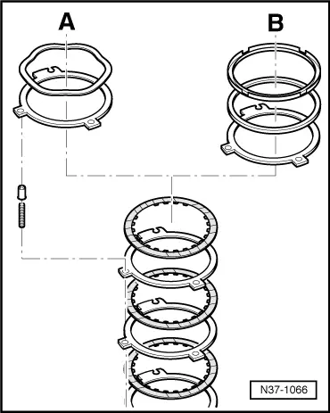
→ There are two types of gearboxes: |
 |
|
|
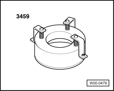
Special tools and workshop equipment required
|
 |
|
|
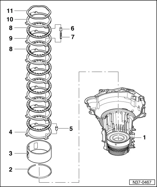
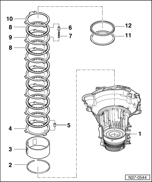
Adjusting 2nd and 4th gear brake -B2- This adjustment instruction is only valid for gearboxes where a corrugated spring washer in brake -B2- on the last outer plate is installed (=> Items 10 and 11). Gearbox code letters => from Page 00-3. On these gearboxes the play of brake -B2- is determined by the thickness of the last outer plate(s) -Item 10-. Note: Adjusting gearboxes without corrugated spring washer. |
|
|
|
|
|
|
|
|
|
 |
||||||||||||
|
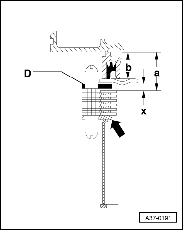
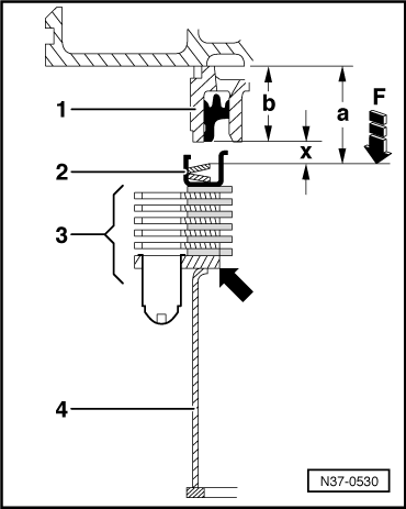
Calculating thickness of last outer plate -D- → The thickness of the outer plate(s) is determined by gap "x". Gap "x" is calculated using the following formula: x = a - b - 3.6 mm
The illustration shows a cross-section of the brake -B2- in assembled form. Special tool 3459, which exerts a force onto the set of plates, is not illustrated. 3.6 mm is the allowance for settling resulting from the force exerted by special tool 3459. Note: The first outer plate -arrow- is 3 mm thick. Calculating measurement "a" Assemble planetary gearbox up to the last -B2- inner plate,
|
 |
||||||
|
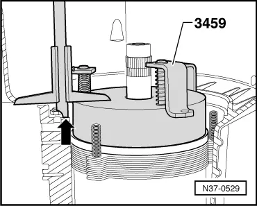
Note: The plate set for -B2- is now pressed together for measurements.
Dimension a = Height of 3459 in mm - measured value Example:
|
 |
|||||||||||||||||||||||||||||||
|
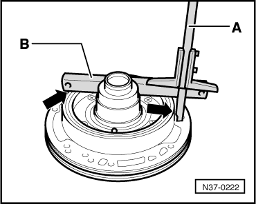
Calculating measurement "b"
Example:
x = a - b - 3.6 mm = 30.2 mm - 20.6 mm - 3.6 mm = 6.0 mm
=> Parts catalogue Table of outer plates -D-
|
 |
|
|
Adjusting 2nd and 4th gear brake -B2- These adjustment procedures are only valid for gearboxes with a shim and retaining ring installed in brake -B2- Gearbox code letters => from Page 00-3. In these gearboxes the play in brake -B2- is determined by the thickness of the shim -Item 11-. Note: Adjusting gearboxes with corrugated spring washer=> Page 37-157. |
|
|
|
|
|
|
|
|
 |
|||||||||
|
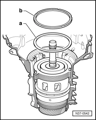
→ Determining thickness of shim(s) The thickness of the shim depends on the size of gap "x". Gap "x" is calculated using the following formula: Gap x = a - b - 2.65 mm
The illustration shows a cross-section of the brake -B2- in assembled form. Special tool 3459, which exerts a force -F- onto the set of plates, is not illustrated. 2.65 mm - The amount for settling is taken into account by force F.
Notes:
|
 |
|
|
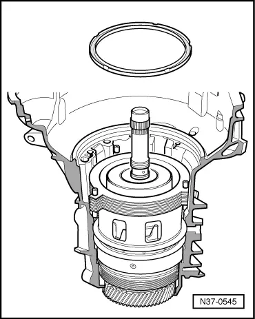
Calculating "a": Assemble planetary gearbox up to the last -B2- inner plate, => Page 37-113. The last outer plate and shim are not installed.
Note: The plate set for -B2- is now pressed together for measurements. |
|
||||||
Dimension a = Height of 3459 in mm - measured value Example:
|
 |
|
|