audi Workshop Repair Guides

Audi Workshop Service and Repair Manuals

Installing > < Removing and installing gearbox
Automatic Gearbox 01VFWD and 4WD
Removing and installing gearbox
Removing

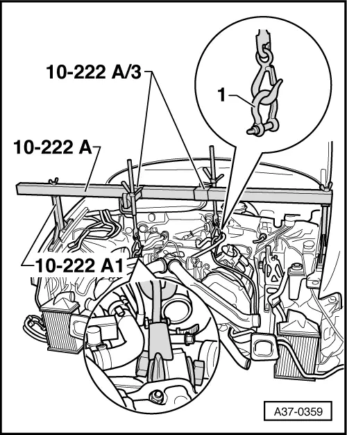
The following special tools and testing devices are required:

    • ‒ 10-222 A - Support bar
    • ‒ 10-222 A/1 - Frame for support bar
    • ‒ 10-222 A/3 Adapters x 2
    • ‒ V.A.G.1383A - Jack
    • ‒ 3282 - Gearbox support
    • ‒ 3282/19 - Adjustment plate
    • ‒ 3282/48 - Locating pin
    • ‒ 3282/52 - Supports x 3
 
G37-0018
    • ‒ V.A.G 1306 - Oil pan
    • ‒ 80-200 - Pressing lever
    • ‒ 3035 Special socket
    • ‒ 3393 Test drifts
    • ‒ Special tool (nut) V 175

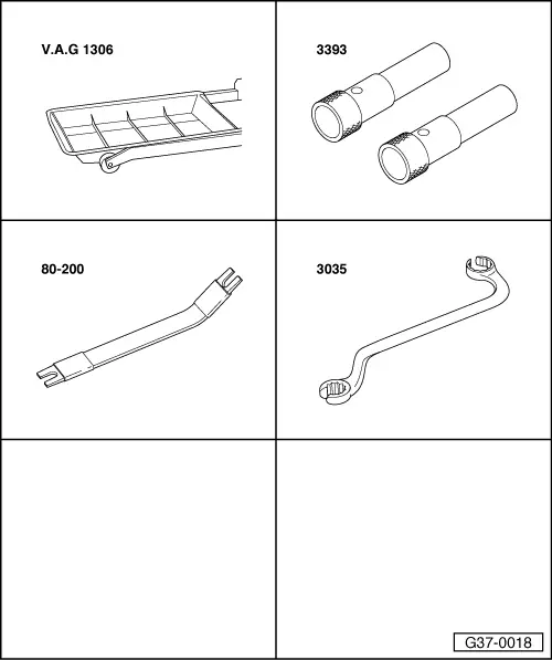
Additionally required information

  • ◆ Workshop Manual A4 1995 ä ; Running Gear, FWD and 4WD
  • ◆ Workshop Manual for Audi A4 1995 ä, Electrical System
  • ◆ Workshop Manual A4 1995 ä, Engine, Mechanical Components
 
A10-0113
  • ‒ Observe or obtain radio code on vehicles with coded radio.
  • ‒ Disconnect earth strap on battery.

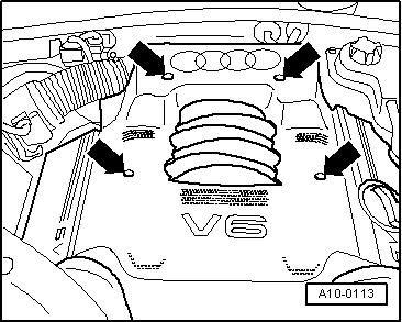
For 6-cylinder petrol engines except 2.7l 5V turbo-charged engine:

  • ‒ → Remove engine cover -arrows-.

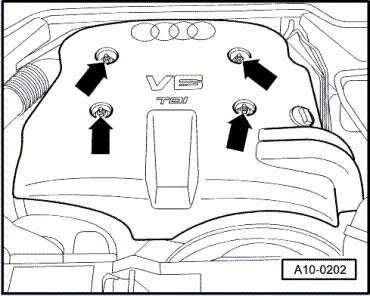
For 6-cyl. diesel direct injection engines (TDI)

 
A10-0202
  • ‒ → Remove engine cover -arrows-.

The remaining procedure for removing and installing the gearbox on 2.7l 5V turbo-charged engines is described from Page => 37-99 onwards.

 
A37-0272

All except 2.7l 5V turbo engine:

  • ‒ Detach covers above air cleaner.
  • ‒ → Remove air guide -1- between air cleaner housing and lock carrier.
  • ‒ Disconnect connector at ACF solenoid -2-, pull solenoid off bracket. Disconnect plug -3- from air mass meter.
  • ‒ Detach intake hose -4- from intake pipe.
  • ‒ Remove upper part of air cleaner.
 
A37-0359
  • ‒ Remove coolant system expansion reservoir and lay to one side.
  • ‒ Unscrew lambda probe from left and right exhaust downpipes.
  • ‒ Unscrew upper securing nuts on front exhaust pipes (left and right).

On all 6-cylinder engines:

  • ‒ Install both adapters 10 -222A/3 for front and rear spindles to support bar.
  • ‒ → Place support bar 10-222 A on wing panel flange using 10-222 A/1.
 
A37-0359
  • ‒ → Attach both spindles to the adapters.
  • ‒ Attach the engine to the spindles. To do this, also use a shackle -1- at the rear of the engine to avoid damage.

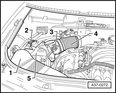
For 4-cylinder engines:

 
A37-0335
  • ‒ → Disconnect plug -A- from bracket -B-
 
A37-0281
  • ‒ Assemble adapter 10-222 A/3 for front spindle on support bar.
  • ‒ → Fit support bar 10-222 A with legs 10-222 A/1 and support engine/gearbox in this position.

All models:

  • ‒ Slightly pre-tension engine/gearbox assembly on the spindles.
  • ‒ Leave the rear spindle slightly loose to allow subsequent lowering to the rear.
  • ‒ Raise vehicle.
  • ‒ Remove front wheels.
 
A10-0018
  • ‒ → Remove noise insulation tray.

 
A37-0061
  • ‒ → Remove heat shields for drive shafts (left and right) -arrows-.
  • ‒ Unbolt drive shafts from flanges on gearbox.

=> Running Gear, Front and Four-wheel Drive; Repair group 40; Removing and installing drive shaft

 
A37-0271
  • ‒ → Remove engine speed sender -G28 arrow B- at front left from gearbox (if fitted).
  • ‒ Unplug connector for speedometer -arrow A- from gearbox.

 
A37-0062
  • ‒ → Remove bracket for noise insulation -1-.
  • ‒ Swivel the retaining lever -4-, and disconnect the plug for the gearbox cable loom.
  • ‒ Pull connector -2- off wiring of multifunction switch.
  • ‒ Unbolt retainer -3- for connector.
 
A37-0079

For 6-cylinder engines except 2.7l 5V turbo-charged engine:

  • ‒ → Unclip the breather hose for the alternator -1-.
  • ‒ Unscrew bracket for ATF wiring -2- at oil pan.

 
A37-0080
  • ‒ → Separate ATF lines -1- from ATF cooler.
  • ‒ Plug ATF lines with clean plugs.
  • ‒ Unbolt retainer for ATF line arrow -3-.
  • ‒ Unscrew starter bolt on gearbox side -2-.
 
A37-0330

Vehicles with 4-cylinder engine

  • ‒ Unscrew bolt -12- to separate the bracket for ATF line -11- from engine.
  • ‒ Unscrew bolt -1-.
  • ‒ Pull lines -2- and -3- out of gearbox.
  • ‒ Plug lines and openings at gearbox with clean plugs.
  • ‒ Put lines to the side in order not to damage them.

All except 2.7l 5V turbo engine:

 
N37-0477
  • ‒ Remove starter.

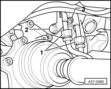
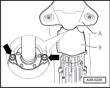
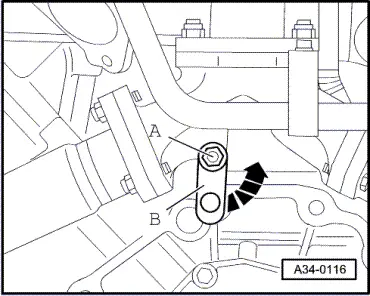
=> Electrical System; Repair group 27; Removing and installing starter

Separate the torque converter from the drive plate.

Foe vehicles with hexagon bolts:

  • ‒ → Unscrew the 3 torque converter bolts with special tool V 175 from the drive plate (turn crankshaft a further 1/3 turn each time).
 
A37-0348

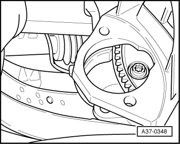
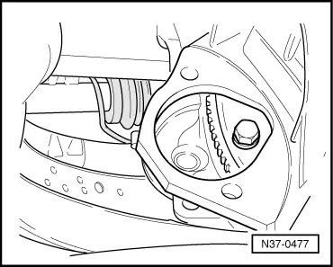
For vehicles with Torx bolts:

  • ‒ → Unscrew the 3 torque converter bolts with an appropriate Torx socket from the drive plate (turn crankshaft a further 1/3 turn each time).

Vehicles with four-wheel drive

 
A39-0220
  • ‒ → Remove heat shield -A- over propshaft.
  • ‒ If necessary, remove the rear part of the exhaust system:
    => corresponding Workshop Manual for Engine, Mechanical Components; Repair group 26; Removing and installing exhaust system
  • ‒ Remove heat shield -B- for propshaft from Torsen differential cover -arrows-.

 
A34-0128
  • ‒ Unbolt the propshaft at the gearbox. Suspend or support the propshaft.
 
A37-0064

Continued for all vehicles

  • ‒ → Set up gearbox support 3282.

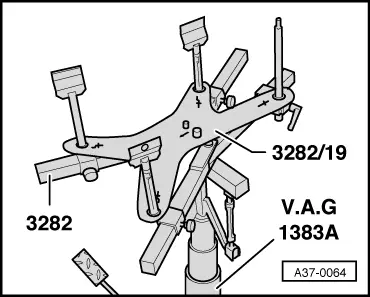
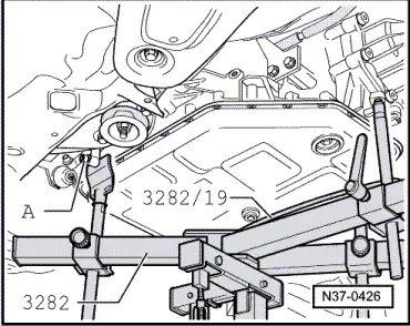
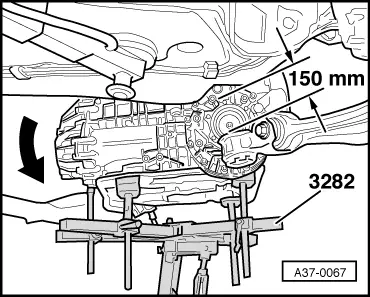
The gearbox support 3282 is aligned with the adjusting plate 3282/2 for removing the automatic gearbox 01V.

The symbols on the adjusting plate indicate the mounts required, the arrow points forward.

 
N37-0426
  • ‒ → Move jack V.A.G 1383 A with gearbox support 3282 under the gearbox and support gearbox.
  • ‒ Align adjustment plate parallel to gearbox.
  • ‒ Secure gearbox to gearbox support 3282 with bolt -A-.

The automatic gearbox 01V with 4WD is supported at the same points as the FWD type.

  • ‒ Remove gearbox support on left and right with gearbox mounting
 
A37-0268
  • ‒ → Unscrew multifunction switch -F125 to protect it from damage -arrows- and expose wiring harness.

 
A37-0063
  • ‒ → Mark position of mounting bracket for selector lever cable to gearbox housing for reinstalling, unscrew mounting bracket -arrows-.
 
A37-0066
  • ‒ If present press off retaining clip -arrow- at end of selector lever cable.

 
N37-0419
  • ‒ → Lever selector lever cable off lever/selector shaft -arrow-.
  • ‒ Remove upper engine/gearbox connecting bolts.

For 6-cylinder TDIengines

 
A34-0116
  • ‒ → Slacken bolt -A- (on rear of turbocharger) by a few turns and pivot strut -B- to one side in direction of arrow. Then tighten bolt -A- again slightly.

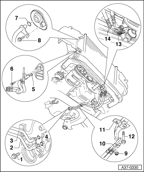
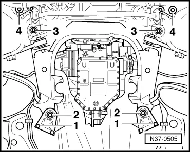
Note:

The illustration shows the engine from the rear with the gearbox removed.

Continued for all vehicles

 
A40-0125
  • ‒ → Before undoing the subframe, use special tool 3393 to check that at least holes -1- and -2- line up.

If this is not the case, check axle alignment after installing the subframe.

 
N37-0505
  • ‒ → Unscrew bolts -1- and -2- at rear of subframe on both sides of vehicle.
  • ‒ Completely unscrew bolts -3- at front of subframe on both sides of vehicles.

The subframe is lowered by approx. 150 mm by releasing bolts on rear edge => Page 37-88, Fig. A37-0067.

  • ‒ Lower rear of engine/gearbox assembly slightly with jack V.A.G 1383 A.
  • ‒ Remove front exhaust.
    => corresponding Workshop Manual for Engine, Mechanical Components; Repair group 26; Removing and installing exhaust system
 
N37-0504
  • ‒ Remove the remaining bolts connecting the engine to the gearbox.
  • ‒ Press gearbox off engine; when doing this, press torque converter out of drive plate.
  • ‒ → Press torque converter against ATF pump -arrow-.

 
A37-0067
  • ‒ → Swivel in gearbox -arrow- and remove carefully between subframe and vehicle underbody.
  • ‒ Lower gearbox.
  • ‒ Secure torque converter to prevent it falling out.

Installing > < Removing and installing gearbox