
A4 Mk1
|
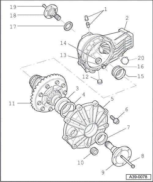
Removing and installing differential
Removing and installing differential
|
 |
|
|
Notes:
|
|
|
|
|
|
|
|
 |
|
|
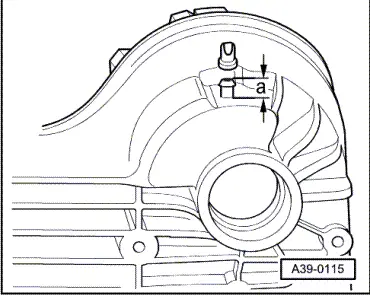
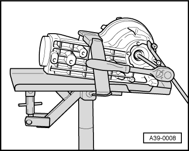
→ Fig2 Press in cover until stop |
 |
|
|
Removing and installing differential
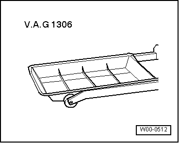
Special tools, testers and auxiliary equipment required
Removing
|
 |
|
|