audi Workshop Repair Guides

Audi Workshop Service and Repair Manuals

Checking hydraulic bucket tappets > < Removing and installing camshaft oil seal
4-Cyl. TDI®Engine, Mechanics
Servicing valve gear
Removing and installing camshaft
 
W00-0992

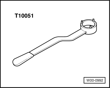
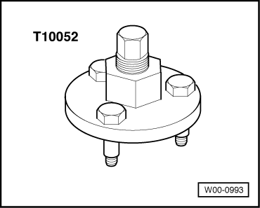
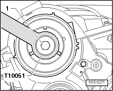
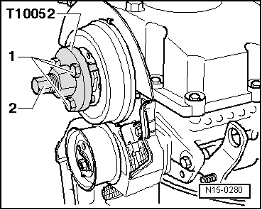
Special tools and workshop equipment required
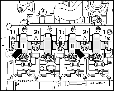
  • ◆ Counterhold T10051

 
W00-0993
  • ◆ Puller T10052
 
N15-0232

Removing

  • ● Cylinder head fitted
  • ● Lock carrier in service position =>Page 13-1.
  • ‒ Remove toothed belt => Page 13-36.
  • ‒ → Screw out camshaft sprocket bolts -1-.
  • ‒ Detach camshaft sprocket from hub.

 
N15-0271
  • ‒ → Slacken hub bolt -1-. Use counterhold T10051.
  • ‒ Screw out hub bolt approx. 2 turns.
 
N15-0280
  • ‒ → Position puller T10052 and screw bolts -1- into hub.
  • ‒ Detach hub by bracing against hexagon (A/F 30) of puller and screw in bolt -2-.
  • ‒ Detach hub from camshaft cone.
  • ‒ Remove cylinder head cover => Page 15-10.

 
A15-0531
  • ‒ → Mark the valve lever shafts with a waterproof marker to avoid them being interchanged and consequently having to reset the pump/nozzle unit -arrows-.
  • ‒ First slacken the two outer bolts -1- on the valve lever shafts, then the inner bolts -2-.
  • ‒ Detach valve lever shafts.
  • ‒ Remove tandem pump:

=> Fuel supply - Diesel engines; Repair Group 20

 
A15-0532
  • ‒ → First remove bearing covers 1, 3 and 5. Unfasten bearing caps 2 and 4 alternately and diagonally.

Notes:

  • ◆ Take care not to interchange camshaft bearing shells.
  • ◆ Use waterproof felt-tip pen to mark assignment of camshaft bearing shells on back.
  • ‒ Take out camshaft.

 
A13-0350

Installing

Install in reverse order, paying attention to the following:

  • ● → Crankshaft toothed belt locked at cylinder 1 TDC with crankshaft stop T10050.
 
A15-0530

Notes:

  • ◆ Do not interchange used bearing shells (pay attention to marking).
  • ◆ When installing camshaft, make sure tabs of bearing shells are correctly seated in bearing covers and cylinder head.
  • ‒ Lubricate camshaft contact surfaces.
  • ‒ Mount camshaft at cylinder 1 TDC position:
    • ‒ → On the camshaft the cams for cylinder 1 must all point uniformly upwards -arrows-

 
A15-0532
  • ‒ → Tighten bearing caps 2 and 4 alternately and diagonally.
 
N15-0270
  • ‒ → Apply a thin, even coat of sealant to the surfaces -1- of bearing covers 1 and 5.
  • ◆ Sealant

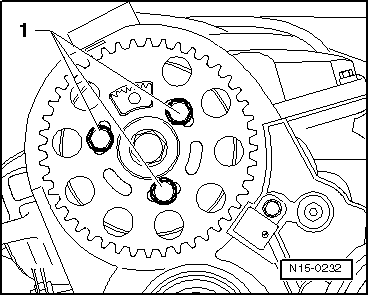
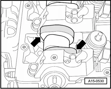
=> Parts List

Note:

Make sure no sealant gets into the grooves -arrows- or onto the other surfaces.

 
A15-0532
  • ‒ → Install bearing covers 1, 3 and 5 in place, and tighten them too.

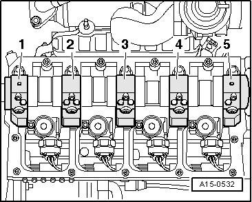
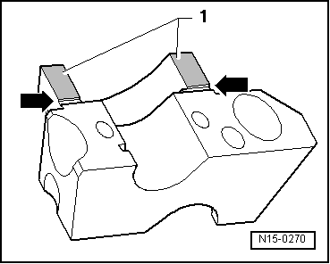
Note:

Bearing cover 5 must abut flush with the outer edge of the cylinder head, otherwise the tandem pump may leak.

  • ‒ Install camshaft oil seal => Page 15-55.
 
A15-0531
  • ‒ → Insert valve lever shafts. Refit to markings made during removal
    -arrows-.
  • ‒ First tighten the inner bolts -2- and then the outer bolts -1- in several alternating stages.

 
N15-0271
  • ‒ Mount hub on camshaft.
  • ‒ → Tighten bolt -1-, bracing with counterhold T10051.
 
N15-0275
  • ‒ → Push camshaft sprocket onto hub.

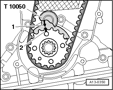
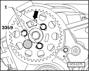
Note:

The tooth segment -arrow- of the camshaft sprocket must be at the top.

  • ‒ Screw bolts -1- in hand-tight.
    • ‒ The camshaft sprocket must just about still turn, and must not tilt.
  • ‒ Arrest hub with rig pin 3359.
  • ‒ Install toothed belt (adjust valve timing) => Page 13-44.
  • ‒ Install tandem pump:

=> Fuel supply - Diesel engines; Repair Group 20-

Notes:

  • ◆ Engine is not to be started for approx. 30 minutes after installing camshaft, so as to allow hydraulic valve lifters to settle (valves would otherwise strike piston).
  • ◆ After working on valve gear, carefully crank engine through at least 2 revolutions to ensure that no valves make contact on starting.
  • ‒ If the valve lever shafts or ball pins and adjuster screws were replaced, you must adjust the pump/nozzle unit:

=> TDIfuel-injection and preheating system(4-cyl. pump/nozzle unit); Repair Group 23; Servicing diesel direct injection system; Removing and installing pump/nozzle unit

  • ‒ Install cylinder head cover => Page 15-12.

Tightening torques

Component

Nm

Bearing cap to cylinder head

8 + 90°1)2)

Valve lever shaft

20 + 90°1)2)

Hub to camshaft

100

    1)    90°corresponds to quarter of a turn

    2)    Replace bolts

Checking hydraulic bucket tappets > < Removing and installing camshaft oil seal