
A4 Mk1
 Note
Note
|
|
|
 Caution
|
|
|
|
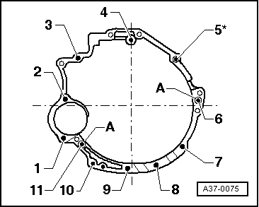
| Item | Bolt | Nm | ||
| 1, 3, 4 | M12x67 | 65 | ||
| 2, 6 | M12x90 | 65 | ||
| 5 *), 11 | M12x110 | 65 | ||
| 7 … 10 | M10x45 | 45 | ||
| A | Dowel sleeves for centralising | |||
| ||||
|
|
| Item | Bolt | Nm | ||
| 1, 8, 9, 10 | M10x45 | 45 | ||
| 2, 3, 4, 11 | M12x67 | 65 | ||
| 5 *) | M12x110 | 65 | ||
| 6 | M12×90 | 65 | ||
| 7 | M10x60 | 45 | ||
| A | Dowel sleeves for centralising | |||
| ||||
|
Note
Note
|
|
| Component | Nm | |
| Bolts/nuts | M6 | 10 |
| M7 | 15 | |
| M8 | 20 | |
| M10 | 45 | |
| M12 | 65 | |
| Except for the following: | ||
| Engine mounting to subframe | 25 | |
| Engine support to engine mounting | 25 | |
| Torque converter to drive plate | 85 | |
| Catalytic converter to turbocharger | 30 | |
| Bracket for ATF pipes | 10 | |
| Power steering pump to bracket | 23 | |
| Pulley to power steering pump | 23 | |
| Viscous fan to bearing | 45 | |
| A/C compressor to bracket | 25 | |
| Stop for torque reaction support to sump | 28 | |
| Hose clips for coolant hoses | 2 | |
| Hose clips for air hoses | 3.5 | |