audi Workshop Repair Guides

Audi Workshop Service and Repair Manuals

Valve gear > < Intake manifold - exploded view
Removing and installing intake manifold
   
Removing
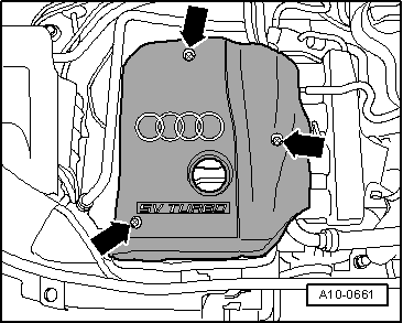
–  Release quick-release fasteners and remove engine cover panel -arrows-.
–  Drain coolant → Chapter.
  A10-0661
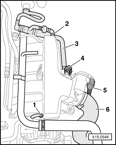
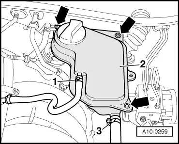
–  Detach coolant hoses -1 and 3-.
–  Unbolt coolant expansion tank -2--arrows-.
–  Detach electrical wiring at coolant shortage indicator switch -F66- on coolant expansion tank (bottom).
  A10-0259
–  Detach vacuum hoses -1 ... 3-.
–  Unplug electrical connectors:
4 - On intake air temperature sender -G42-
5 - On throttle valve module -J338-
–  Disconnect air hose -6- from throttle valve module.
  A15-0548
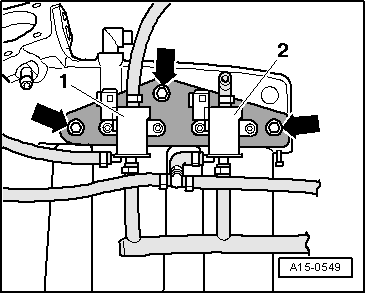
–  Unbolt retaining plate for solenoid valves -arrows- located below intake manifold.
  Note
The electrical connectors -1 and 2- and vacuum hoses remain attached.
  A15-0549
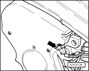
–  Unplug electrical connector -arrow- at Hall sender -G40-.
  A15-0128
–  Remove bolts for fuel rail and disconnect vacuum line from fuel pressure regulator -arrows-.
–  Pull fuel rail together with injectors off intake manifold and set it aside on a clean cloth in rear of engine compartment.
  Note
Make sure the removed injectors do not become soiled.
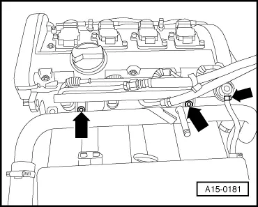
  A15-0181
–  Detach coolant hoses from top coolant pipe.
–  Move electrical wiring on top coolant pipe clear.
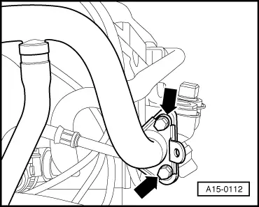
–  Unbolt top coolant pipe from intake manifold and from coolant flange on rear of cylinder head -arrows-.
  A15-0112
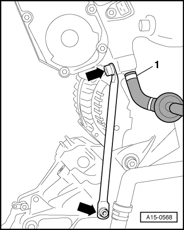
–  Remove support for intake manifold -arrows-.
–  Detach hose -1- leading to solenoid valve 1 for activated charcoal filter -N80- from intake manifold.
–  Pull out oil dipstick.
–  Remove bracket for dipstick guide tube.
–  Unbolt intake manifold from cylinder head and remove.
  Note
Block off intake ports in cylinder head with clean rags.
Installing
Installation is carried out in the reverse order; note the following:
  Note
t  Renew gaskets and O-rings.
t  Hose connections and hoses for charge air system must be free of oil and grease before assembly.
t  Secure all hose connections with the correct type of hose clips (same as original equipment) → Parts catalogue.
–  Observe notes on procedure for connecting the battery → Rep. Gr.27.
–  Fill up with coolant → Anchor.
Tightening torques
  A15-0568
ComponentNm
Intake manifold to cylinder head10
Support for intake manifold to:Bracket for ancillaries20
Intake manifold20
Coolant pipe (top) to:Intake manifold10
Coolant flange10
Fuel rail to intake manifold10
Hose clips for coolant hoses2
Hose clips for air hoses3.5


Valve gear > < Intake manifold - exploded view