audi Workshop Repair Guides

Audi Workshop Service and Repair Manuals

Checking secondary air pump relay J299 and secondary air pump motor V101 > < Checking combination valve for secondary air system for proper operation and leakage
Checking secondary air inlet valveN112
   
Checking secondary air inlet valve -N112-
Special tools and workshop equipment required
t  Hand-held multimeter -V.A.G 1526C-
t  Voltage tester -V.A.G 1527B-
t  Auxiliary measuring set -V.A.G 1594C-
t  Adapter cable, 121-pin -V.A.G 1598/31- (test box)
t  Vehicle diagnostic, testing and information system -VAS 5051B-

   
Procedure
  Note
The secondary air inlet valve -N112- and the wiring connections are monitored by the engine control unit.
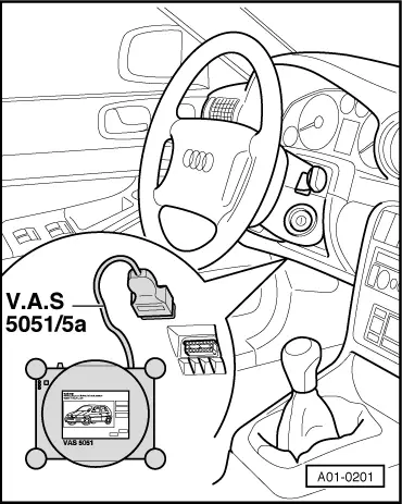
l  Vehicle diagnostic, testing and information system -VAS 5051B- connected.
–  Switch on ignition and start engine.
  A01-0201
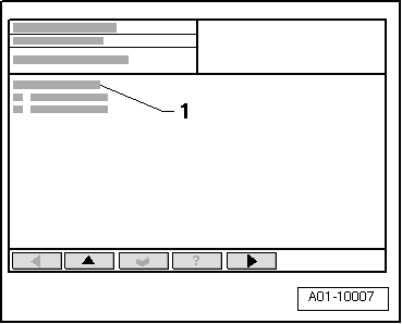
Display on -VAS 5051B-:
–  From menu -1-, select “Self diagnosis” system and press key to activate function.
  A01-10007
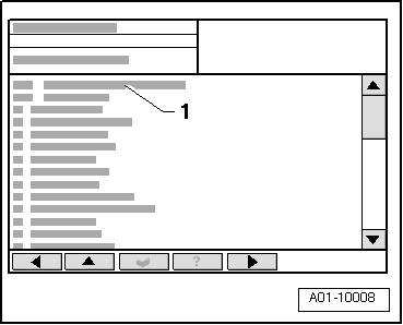
Display on -VAS 5051B-:
–  From menu -1-, select vehicle system “01 - Engine electronics” system and press key to activate function.
  A01-10008
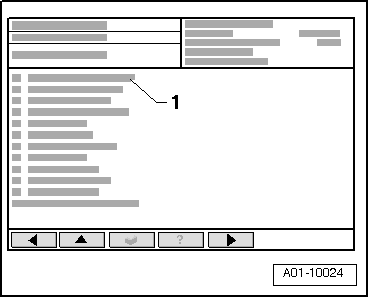
Display on -VAS 5051B-:
–  From menu -1-, select diagnostic function “004 - Fault memory contents” and press key to activate function.
  A01-10024
Display on -VAS 5051B-:
–  From menu -1-, select diagnostic function “004.01 - Interrogate fault memory” and press key to activate function.
If a fault relating to secondary air inlet valve -N112- is displayed:
–  Terminate diagnostic function “004.01 - Interrogate fault memory” by touching key.
–  Select diagnostic function “022 - End output” and switch off ignition.
  A01-10007
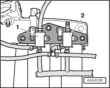
–  Disconnect hoses from secondary air inlet valve -N112--item 2-; leave electrical connector attached.
t  Fitting location: below intake manifold.
  Note
For illustration purposes, the installation position is shown from the bottom and with the intake manifold removed.
  A24-0239
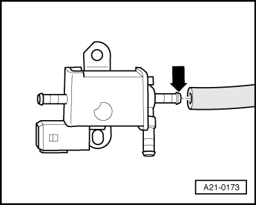
–  Connect test hose to the hose connection on the solenoid air inlet valve -N112- marked with an -arrow-.
  A21-0173
–  Switch on ignition and select vehicle system “01 - Engine electronics” again.
Display on -VAS 5051B-:
–  From menu -1-, select diagnostic function “005 - Final control diagnosis” and press key to activate function.
  A01-10024
–  Press the key repeatedly until the following display appears:
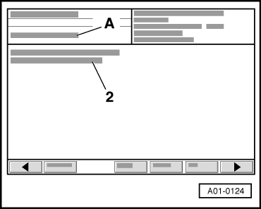
Display on -VAS 5051B- (example):
A - 2nd control element being tested
2 - Secondary air inlet valve -N112-
l  The valve will be activated intermittently for approx. 1 minute (and should click audibly).
l  The valve should open and close (check by blowing into the test hose).
–  Terminate diagnostic function “005 - Final control diagnosis” by touching key.
–  Select diagnostic function “022 - End output” and switch off ignition.
If the valve is not activated (does not click):
  A01-0124
Checking internal resistance
–  Unplug electrical connector at secondary air inlet valve -N112--item 2-.
  A24-0239
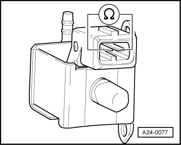
–  Connect hand-held multimeter -V.A.G 1526C- to measure resistance between contacts on secondary air inlet valve -N112-.
l  Specification: 27 ... 30 Ω.
–  If the specification is not attained, renew secondary air inlet valve -N112-.
If the specification is attained:
Checking voltage supply
l  Fuse for secondary air inlet valve -N112- OK → Current flow diagrams, Electrical fault finding and Fitting locations.
l  Fuel pump relay -J17- OK; checking → Rep. Gr.24
  Note
The secondary air inlet valve -N112- is supplied with power via the fuel pump relay -J17-.
  A24-0077
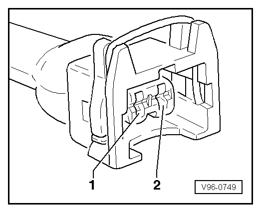
–  Connect voltage tester -V.A.G 1527B- between contact -1- of connector for secondary air inlet valve -N112- and earth “–”.
–  Briefly operate starter.
l  The LED should light up.
–  If LED does not light up, check for open circuit in wiring from contact -1- of connector for secondary air inlet valve -N112- via fuse to fuel pump relay -J17- → Current flow diagrams, Electrical fault finding and Fitting locations.
–  If necessary repair wiring connection.
If the LED lights up:
  V96-0749
Checking activation
–  Connect voltage tester -V.A.G 1527B- between contacts -1- and -2- of connector for secondary air inlet valve -N112-.
  V96-0749
–  Switch on ignition and select vehicle system “01 - Engine electronics” again.
–  Repeat diagnostic function “005 - Final control diagnosis”.
–  Press the key repeatedly until the following display appears:
Display on -VAS 5051B- (example):
A - 2nd control element being tested
2 - Secondary air inlet valve -N112-
l  The LED should flash.
  A01-0124
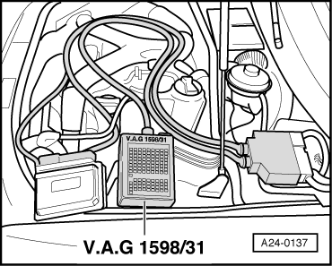
–  If LED does not flash or lights up continuously, connect adapter cable, 121-pin -V.A.G 1598/31- (test box) to connectors of wiring harness; do not connect engine control unit. Connect earth clip of test box to earth → Rep. Gr.24.
  A24-0137
–  Check for open circuit and short to positive or earth in the following wiring for secondary air inlet valve -N112-.
  V96-0749
Connector
Contact
-V.A.G 1598/31-
Socket
-2-9

–  If necessary repair wiring connection.
   

Checking secondary air pump relay J299 and secondary air pump motor V101 > < Checking combination valve for secondary air system for proper operation and leakage