
A4 Mk1
| Secondary air system - exploded view of components |

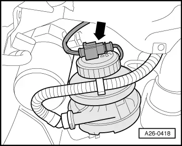
| 1 - | Secondary air pump motor -V101- |
| q | Fitting location → Fig. |
| q | Checking voltage supply → Anchor |
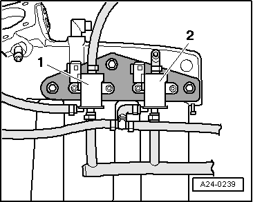
| 2 - | Air cleaner |
| 3 - | Combination valve for secondary air system |
| q | Fitting location → Fig. |
| q | Checking for correct operation and leakage → Chapter. |
| 4 - | Non-return valve |
| q | Installation position: as shown in illustration, the arrow points in direction of flow |
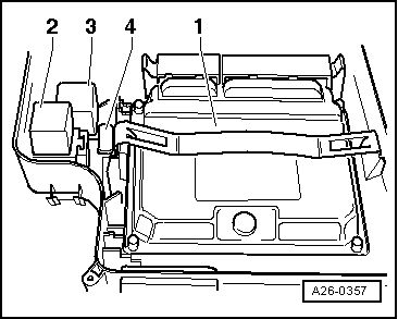
| 5 - | Secondary air pump relay -J299- |
| q | Fitting location → Fig. |
| q | Checking → Chapter |
| 6 - | Motronic control unit -J220- |
| 7 - | Vacuum reservoir |
| q | Fitting location: in front left wheel housing beneath liner |
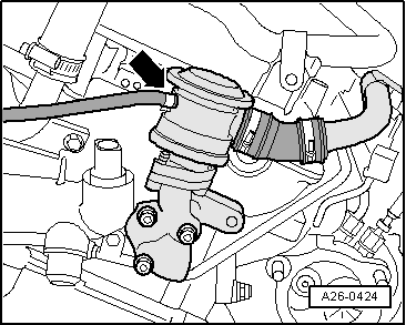
| 8 - | Secondary air inlet valve -N112- |
| q | Fitting location → Fig. |
| q | Checking → Chapter |
| 9 - | Cylinder head |
|
|
|
|
 Note
Note
|
|