
A4 Mk1
| Removing and installing thermostat |

| Special tools and workshop equipment required |
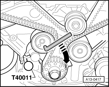
| t | Locking pin -T40011- |
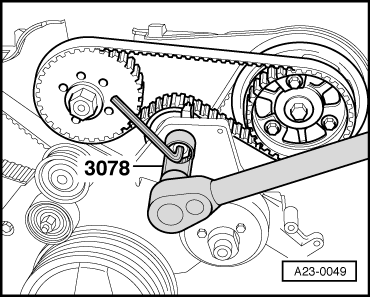
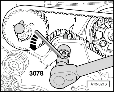
| t | Socket (22 mm) -3078- |
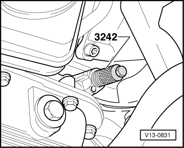
| t | Locking pin -3242- |
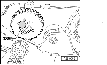
| t | Diesel injection pump locking pin -3359- |
| t | Locking fluid → Electronic parts catalogue |
|
|
 Note
Note
|
|
 Caution
Note
|
|
 WARNING
|
|
|
|
Note
|
|
|
|
Note
|
|
Note
|
|
|
|
Note
|
|
|
|
|
|
|
|
|
|
|
|
|
|
Note
|
|
|
|
|
|
|
|
| Component | Nm |
| Vibration damper to injection pump sprocket | 22 |
| Drive sprocket for injection pump to camshaft | 22 |
| Vibration damper to crankshaft sprocket | 22 |
| Screw plug in cylinder block | 10 |
| Tensioning roller for injection-pump toothed belt to bracket for viscous fan | 36 |
| Viscous fan pulley to hub | 10 |
| Viscous fan to bearing | 70 |