
A4 Mk1
| Checking exhaust gas temperature sender |

| Special tools and workshop equipment required |
| t | Hand-held multimeter -V.A.G 1526 C- or -V.A.G 1526 A- |
| t | Voltage tester -V.A.G 1527 B- |
| t | Auxiliary measuring set -V.A.G 1594 C- or -V.A.G 1594 A- |
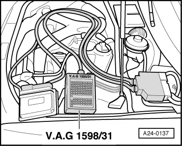
| t | Adapter cable -V.A.G 1598/31- (test box) |
|
|
 Note
Note
Note
|
|
|
|
|
|
 Caution
|
|
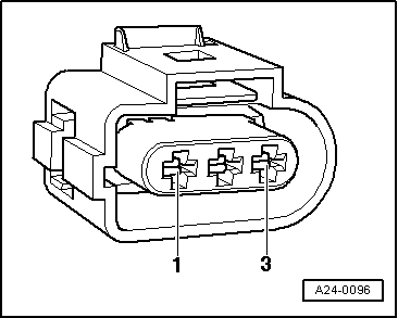
| Component | Connector Contact | Adapter cable, 121-pin -V.A.G 1598/31- Socket |
| Exhaust gas temperature sender 1 -G235- Bank 1 (right-side) | -1- (signal) | 61 |
| -2- (earth) | 62 | |
| Exhaust gas temperature sender 1, bank 2 -G236- Bank 2 (left-side) | -1- (signal) | 20 |
| -2- (earth) | 62 |
|