
A4 Mk1
|
|

|
|
|
 Note
Note
|
|
Note
|
|
|
|
Note
|
|
| Component | Nm | ||
| Exhaust gas temperature sender 1 -G235- to turbocharger | 27 | ||
| Control unit for exhaust gas temperature sender to intake manifold | 8 1) | ||
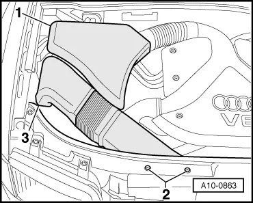
| Air duct to intake manifold | 10 | ||
| |||