
A4 Mk1
|
|
|
 Note
Note
|
|
|
|
|
|
Note
|
|
Note
|
|
|
|
|
|
|
|
|
|
|
|
|
|
|
|
|
|
|
|
|
|
Note
|
|
|
|
Note
|
|
| Component | Nm | ||
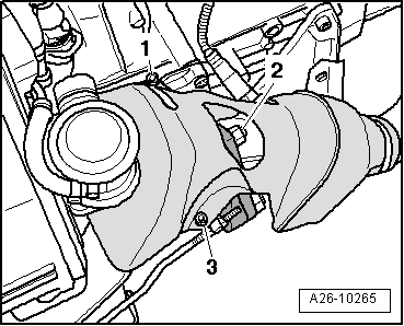
| Exhaust gas temperature sender 1, bank 2 -G236- to exhaust manifold | 27 | ||
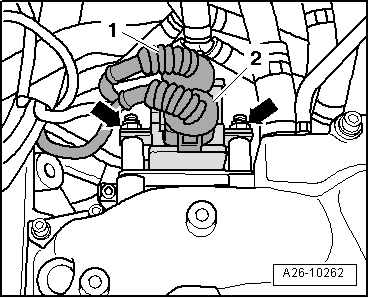
| Control unit for exhaust gas temperature sender to intake manifold | 8 1) | ||
| Lambda probe to front exhaust pipe | 55 | ||
| Heat shield for front exhaust pipe | 10 | ||
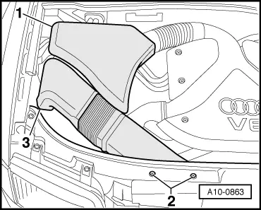
| Air duct to intake manifold | 10 | ||
| Drive shaft heat shield to gearbox | 23 | ||
| |||