audi Workshop Repair Guides

Audi Workshop Service and Repair Manuals

Checking charge pressure control > < Connection diagram for charge pressure control and overrun air recirculation control
Checking turbocharger and charge pressure control
Special tools and workshop equipment required
   
t  Turbocharger tester -V.A.G 1397 A-
  W00-0565
t  Vehicle diagnosis, testing and information system -VAS 5051-
  W00-10343
Procedure
–  Unfasten screw connections -top right arrows- and detach engine cover panel (left-side)-B-.
  A34-0163
–  Connect T-piece with test hose of turbocharger tester -V.A.G 1397 A- to fuel pressure regulator -arrow-.
–  Route test hose under rear edge of bonnet and through right window into passenger compartment.
  A21-0054
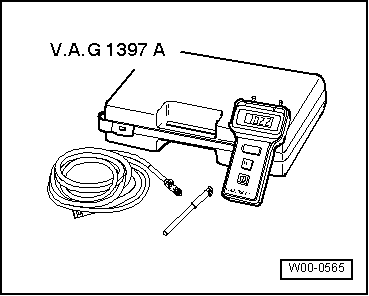
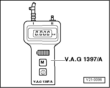
–  Switch on turbocharger tester and set measuring range selector switch to position -I- (absolute pressure).
–  Attach test hose to connection -I-.
  Note
t  Ensure absolute leakproof connection of hoses to avoid measurement errors.
t  Take care not to trap test hose at bonnet and side window.
t  Pressing memory button -M- on turbocharger tester causes last measured value to be stored until memory button -M- is pressed again or tester is switched off.
t  The decimal point in the display flashes to indicate that the value is being stored.
t  If the battery voltage of the turbocharger tester drops below the minimum level, an arrow will appear at the top left of the display.
t  Before performing the test, drive vehicle moderately fast for at least 3 km (without stopping at traffic lights etc.).
  WARNING
To avoid accident risks when road testing the vehicle with test equipment, always observe the relevant safety precautions → Chapter.
  V21-0096
–  Open rear ashtray and remove cover for diagnostic connector.
  A24-0028
–  Connect up vehicle diagnostic, testing and information system -VAS 5051- with diagnosis lead -VAS 5051/1-, press vehicle self-diagnosis button and select vehicle system “01 - Engine electronics”. Engine must be idling.
  A01-0061
Display on -VAS 5051-:
–  From the list -1- select diagnostic function “08 - Read measured value block”.
  A01-0122
Display on -VAS 5051-:
–  Use keypad -2- to enter “115” for “Display group number 115” and confirm by touching the Q key.
1 - Enter display group
–  Accelerate vehicle in 4th gear from 2000 rpm at full throttle while a second mechanic observes the rev counter.
–  Have the second mechanic press PRINT key on -VAS 5051- and memory key -M- on -V.A.G 1397 A- simultaneously at approx. 3000 rpm.
  Note
The charge pressure should be measured using turbocharger tester -V.A.G 1397 A-. Vehicle diagnostic, testing and information system -VAS 5051- is used to check whether the charge pressure is being registered by the control unit.
  A01-0130
l  Specification on -V.A.G 1397 A-: 1.870 ... 1.980 bar.
  V21-0096
l  Specification on -VAS 5051- in display zone -4-: 1870 ... 1980 mbar.
–  Press the  key to exit from the function “08 - Read measured value block”.
If specification is not obtained:
–  Check charge pressure control → Chapter.
–  Find fault causes using fault table below.
  A01-0187
FaultPossible causes
Charge pressure below specification
t  Hose connections to solenoid valve for charge pressure control -N75- defective. Connection diagram → Chapter
t  Solenoid valve for charge pressure control -N75- defective. Checking → Chapter
t  Charge pressure regulating valve in turbocharger stuck in open position. Renewing turbocharger: left-side → Chapter; right-side → Chapter.
t  Leak between turbocharger and intake manifold (air intake hoses and vacuum hoses)
t  Mechanical air recirculation valve defective. Checking → Chapter
t  Turbocharger air recirculation valve -N249- defective. Checking → Chapter
t  Turbocharger defective. Renewing turbocharger: left-side → Chapter; right-side → Chapter.
Charge pressure above specification
t  Air leaks in hoses or connections to pressure unit for charge pressure control (via -N75-). Connection diagram → Chapter
t  Vacuum unit for charge pressure regulating valve defective. Renewing turbocharger: left-side → Chapter; right-side → Chapter.
t  Charge pressure regulating valve in turbocharger sticking in closed position. Renewing turbocharger: left-side → Chapter; right-side → Chapter.

If specification is obtained:
–  Press function “06 - End output”.
–  Switch off ignition and unplug diagnostic connector.
   

Checking charge pressure control > < Connection diagram for charge pressure control and overrun air recirculation control