audi Workshop Repair Guides

Audi Workshop Service and Repair Manuals

Checking clutch pedal switch -F36 > < Adapt kickdown function
Motronic Fuel Injection and Ignition System (4-cyl) Turbo
Checking electronic engine power control (electronic throttle)
Checking brake light switch and brake pedal switch
 
G24-0023

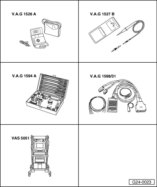
Special tools and workshop equipment required

  • ◆ V.A.G 1526 A
  • ◆ V.A.G 1527 B
  • ◆ V.A.G 1594 A
  • ◆ V.A.G 1598/31
  • ◆ VAS 5051 with VAS 5051/1
  • or
  • ◆ V.A.G 1551 with V.A.G 1551/3 A

Note:

Command from accelerator pedal sender (potentiometer) to engine control unit for opening throttle valve is suppressed for safety reasons when brake is pressed. To do this the control unit requires signals from both the brake light switch and the brake pedal switch.

If the brakes are actuated when the accelerator pedal is held at a constant position, the engine speed is immediately reduced to idling speed. Incorrectly adjusted switches may lead to unwanted regulating actions.

Test sequence

  • ‒ Connect vehicle diagnostic, testing and information system VAS 5051 or fault reader V.A.G 1551 and select engine electronics control unit with "Address word" 01
    For this purpose, the ignition must be switched on.
 
→ When indicated on display:
Rapid data transfer    HELP
Select function XX
  • ‒ Enter "08" to select the function "Reading measured value block" and confirm entry with Q key.
 
→ When adjacent display appears:
Reading measured value block    Q
Enter display group number XXX
  • ‒ Enter "066" for "display group number 066" and confirm entry with Q key.
 
→ Indicated on display:
Read measured value block 66    ⇒
    1    2    3    4
  • ‒ Check brake light/brake pedal switch in display zone 2.

Display zones

1

2

3

4

Display group 066: Signals to engine control unit

Display

xxx km/h

XXXXXXXX

xxx km/h

XXXXXXXX

Display

ACTUAL speed

Switch settings

SPECIFIED speed

Switch settings

Range


XXXXXX00
XXXXXX11

Specified value

XXXXXX00
(with brake pedal
not pressed)

XXXXXX11
(with brake pedal
pressed)

Note:

Value:
X = no meaning.
Switching points are slightly offset

If the display is not as described:

Checking switch

  • ‒ Remove driver's storage compartment.

=> General Body Assembly - Interior; Repair group 68; Dash panel; Removing driver's shelf

  • ‒ Unplug connector from brake light/brake pedal switch.
 
A24-0242
  • ‒ → Connect multimeter between contacts 1 and 2 to measure resistance.
    • ‒ Specified value: ∞ω (no continuity)
  • ‒ Press brake pedal.
    • ‒ Specified value: approx. 0 ω
  • ‒ Connect multimeter between contacts 3 and 4 to measure resistance.
    • ‒ Specified value: approx. 0 ω
  • ‒ Press brake pedal.
    • ‒ Specified value: ∞ω (no continuity)

If specified values are not attained:

  • ‒ Replace brake light/brake pedal switch.

If specified values are attained:

  • ‒ Check the power supply.

Checking power supply

 
A24-0235
  • ‒ → Connect voltage tester V.A.G 1527 B as follows:

Connector
contact

Measure to

1

Car body earth point

    • ‒ The LED should light up.

Connector
contact

Measure to

3

Car body earth point

  • ‒ Switch the ignition on.
    • ‒ The LED should light up.

If the LED does not light up:

  • ‒ Check the wiring between contact 1 and 3 of connector for open circuit/short to earth:

=> Current Flow Diagrams, Electrical Fault-Finding and Fitting Locations

  • ‒ Rectify any open/short circuit as necessary.

If the LED lights up:

  • ‒ Check actuation.

Checking actuation

  • ‒ Connect the V.A.G 1598/31 test box to wiring harness leading to engine control unit; the engine control unit should not be connected => Page 24-19.
 
A24-0235
  • ‒ → Check for open circuit and short to positive or earth in the following wiring connections:

Connector
contact

Test box V.A.G 1598/31
Socket

2

56

4

55

  • ‒ Rectify any open/short circuit as necessary.

Checking clutch pedal switch -F36 > < Adapt kickdown function