audi Workshop Repair Guides

Audi Workshop Service and Repair Manuals

Testing fuel pump relay > < Removing and installing injectors
Motronic fuel injection and ignition system (4-cyl.turbo) > 07.96
Repairing the Motronic fuel injection system
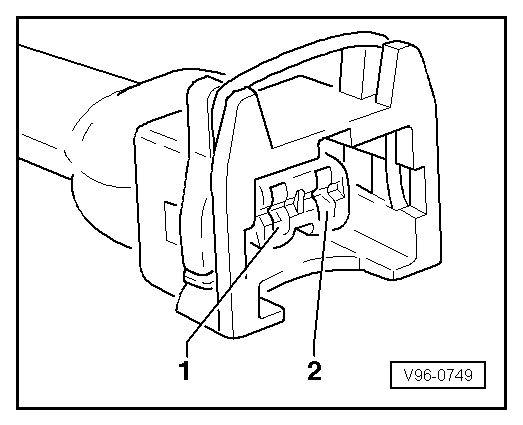
Testing injectors

Electrical checks on injectors

  • ‒ Start actuator diagnosis and activate injectors .
 
→ Indicated on display:
Actuator diagnosis    ⇒
Injector, cylinder 1 -N30
  • ‒ Turn the throttle mechanism on the throttle valve control unit to open the idling switch.
  • The valve should click five times.

If the valve clicks:

  • ‒ Activate the next injector.

If the valve does not click:

 
V96-0749
  • ‒ Remove connector from the injector which is to be tested.
  • ‒ → Connect the V.A.G 1527 diode test lamp between contact 1 and contact 2 in the connector.
  • ‒ Repeat the actuator diagnosis and again actuate the injector.
  • The diode test lamp should flash five times.

Note:

Diode test lamps with a low current consumption do not go out completely between the flashing pulses, but continue to glow slightly and become much brighter during the flashing pulses.

If the diode test lamp does not flash:

  • ‒ Check the voltage supply
    => Page 24-26

If the diode test lamp flashes:

 
A96-0134
  • ‒ → Connect multimeter to valve for resistance measurement
  • Specified result: 11...13 ω

If specified result is not attained:

  • ‒ Renew injector.

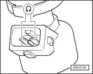
Testing power supply

 
V96-0749
  • ‒ Remove connector from the injector which is to be tested.
  • ‒ → Connect the multimeter for voltage measurement to contact 1 on the connector and to earth.
  • ‒ Operate the starter for a few seconds (the engine can be allowed to start).
  • Specified result: The diode test lamp should light up.

If the diode test lamp lights up:

  • ‒ Check the wiring connections => Page 24-27

If the diode test lamp does not light up:

 
V96-0749
  • ‒ → Check wiring connection from Contact 1 to the fuse for injector.

=> Circuit diagrams, Electrical Fault Finding and Installation Location binder

Check wiring connections

  • ‒ Switch off ignition.
  • ‒ Remove connector from the injector which is to be tested.
  • ‒ Connect the V.A.G 1598/22 test box to the wiring harness for the engine control unit
    => Page 24-6

The following wiring connections should be checked for open circuits and/or short to positive or negative.

 
V96-0749

Cylinder

2-pin connector on the wiring harness contact.

Test box V.A.G 1598/22 socket.

1

2

73

2

2

80

3

2

58

4

2

65

  • ‒ If necessary, rectify open circuit or short circuit.

Testing fuel pump relay > < Removing and installing injectors