
A4 Mk1
|
Servicing Motronic injection system
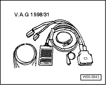
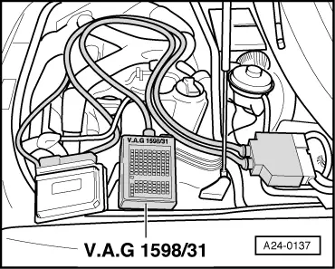
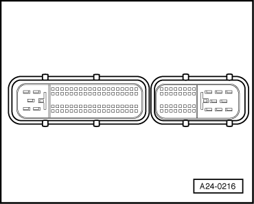
Wiring and component check with test box V.A.G 1598/31
Notes:
Important:
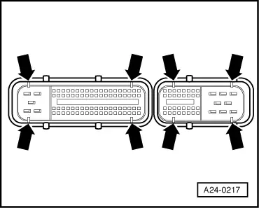
To prevent damage to the electronic components, select appropriate measuring range before connecting the measuring cables and observe the test requirements. |
 |
|
|
Special tools and workshop equipment required
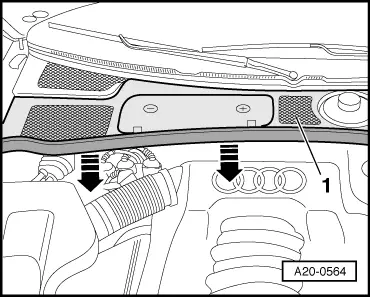
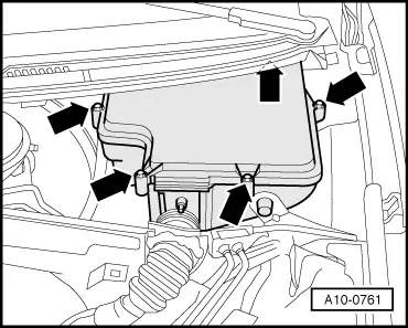
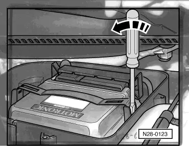
Procedure
|
 |
|
|
 |
|
|
 |
|
Important:
To prevent damage to the electronic components, select appropriate measuring range before connecting the measuring cables and observe the test requirements. |
 |
|
Perform the following operations after re-connection of engine control unit:
Note: In the first learning phase, during the basic setting operation for the engine, slightly irregular idling and slight jolting during driving are possible. Comments on test box V.A.G 1598/31:
|
 |
|
|
 |
|
|