audi Workshop Repair Guides

Audi Workshop Service and Repair Manuals

Fuel pump relay -J17 and actuation > < Remove and install injectors
Motronic Fuel Injection and Ignition System (6-cylinder)
Servicing Motronic injection system
Testing injection quantity, leak tightness and spray pattern of injectors
 
G24-0025

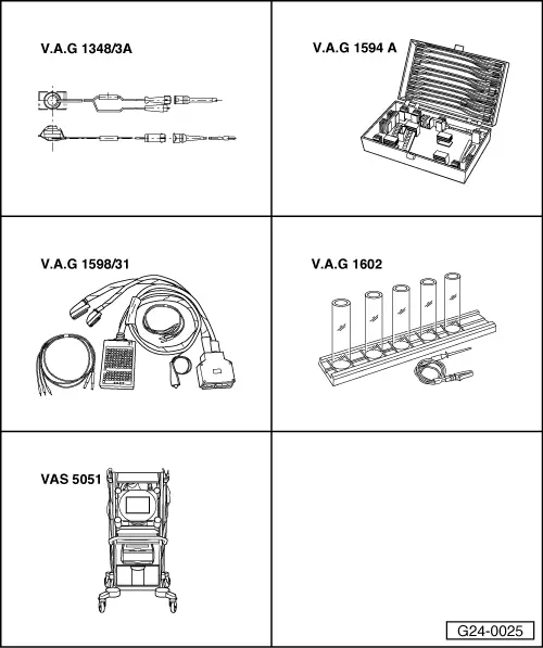
Special tools and workshop equipment required

  • ◆ V.A.G 1348/3A with 1348/3-2
  • ◆ V.A.G 1594 A
  • ◆ V.A.G 1598/31
  • ◆ V.A.G 1602
  • ◆ VAS 5051 with VAS 5051/1
  • or
  • ◆ V.A.G 1551 with V.A.G 1551/3 A

Test requirements:

  • ● Fuel pressure OK, checking .

Test sequence

  • ‒ Remove fuel distributor rail with injectors fitted from intake manifold . Fuel hoses remain connected.
  • ‒ Connect the V.A.G 1598/31 test box to wiring harness leading to engine control unit; the engine control unit should not be connected => Page 24-17.
  • ‒ Bridge contacts 1 and 65 on the test box using test leads from adapter set V.A.G 1594 A (this creates an earth connection to one side of the fuel pump relay coil).

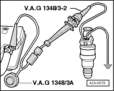
Note:

The fuel pump relay obtains positive supply (terminal 30) directly via central electrical system. The negative voltage supply for the fuel pump relay comes via the cable bridge in the test box. The fuel pump now runs constantly.

Leak test

  • ‒ Check injectors for leaks (visual check). When the fuel pump is running, only 1 or 2 drops a minute should escape from each injector.
 
A24-0069
  • ‒ If the fuel loss is greater switch off fuel pump (remove cable bridge) and replace defective injector => Page 24-47.

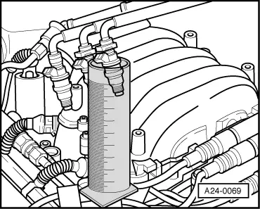
Checking injection quantity

  • ‒ → Place injector to be tested in a measuring glass from injection quantity tester V.A.G 1602.

 
A24-0079
  • ‒ → Connect one of the injector contacts to the engine earth using a test cable and crocodile clip from V.A.G 1594 A.
  • ‒ Connect second contact of injector with remote control V.A.G 1348/3A, adapter lead V.A.G 1348/3-2 and auxiliary cable to positive.
  • ‒ Jumper contacts 1 and 65 at test box with leads from adapter set V.A.G 1594 A.
    • ‒ The fuel pump should run.
  • ‒ Activate the V.A.G 1348/3 A remote control for 30 seconds.
  • ‒ Once all three injectors of a cylinder bank have been actuated, place the three measuring glasses on a flat surface.
    • ‒ Specified value per injector: 90...125 ml
  • ‒ If measured values for one or more injectors are outside tolerance, switch off fuel pump (pull off cable bridge) and replace defective injector => Page 24-47.
  • ‒ Repeat the check on injectors of second cylinder bank.
  • ‒ If the measured values for all the injectors are outside the tolerance range, check the fuel pressure => Page 24-34.

Note:

When checking the injection quantity, also check the spray pattern. The spray pattern should be the same for all the injectors.

  • ‒ Install injectors with fuel distributor rail => Page 24-48.

Fuel pump relay -J17 and actuation > < Remove and install injectors