audi Workshop Repair Guides

Audi Workshop Service and Repair Manuals

Checking engine speed sender -G28 > < Checking ignition coils
Motronic fuel injection and ignition system (6 cyl.)
Checking ignition system
Checking intake air temperature sender -G42
 
G24-0021

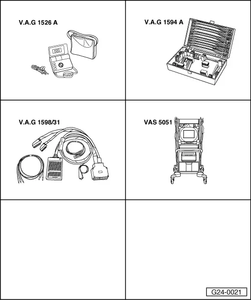
Special tools, testers and workshop equipment required

  • ◆ V.A.G 1526 A
  • ◆ V.A.G 1594 A
  • ◆ V.A.G 1598/31
  • ◆ VAS 5051 with VAS 5051/1
  • or
  • ◆ V.A.G 1551 with V.A.G 1551/3 A

Installation position => Overview installation positions - Page 24-5

Test sequence

  • ‒ Connect up vehicle diagnosis, measurement and information system VAS 5051 or fault reader V.A.G 1551 and select engine electronics control unit with "Address word" 01 .
    When doing this the ignition must be switched on.
 
→ Display readout:
Rapid data transfer    HELP
Select function XX
  • ‒ Enter "08" to select the function "Reading measured value block" and confirm entry with Q key.
 
→ Display readout:
Reading measured value block    Q
Enter display group number XXX
  • ‒ Enter "004" to select "Display Group 004" and confirm entry with the Q key.
 
→ Display readout:
Read measured value block 4    ⇒
    1    2    3    4
  • ‒ Check specified value for intake air temperature sender in display zone 4:

Display zones

1

2

3

4

Display Group 004: Intake air temperature with engine idling

Display

xxxx rpm

xx.x Volt

xxx.x oC

xxx.x oC

Display

Engine speed

Battery voltage

Coolant temperature

Intake air temperature

Range

0...6800 rpm

10.0...15.0 V

-48.0...143.0 oC

-48.0...143.0 oC

Specified value

xxxx rpm

12.0...15.0 V

80.0...110.0 oC

Between ambient temperature and up to 120 oC 1)

1)    Approximate values:

Up to 24 oC in excess of ambient temperature when driving.

Up to 120 oC possible when stationary.

Checking wiring

  • ‒ Connect the V.A.G 1598/31 test box to wiring harness leading to engine control unit; engine control unit should not be connected => Page 24-20.
 
V96-0749
  • ‒ → Check for open circuit and short to earth/positive or earth in the following wiring connections:

Connector
Contact

Test box V.A.G 1598/31
Bush

1

85

2

108

  • ‒ Check for shorts between the two lines.
  • ‒ Rectify any open/short as necessary.

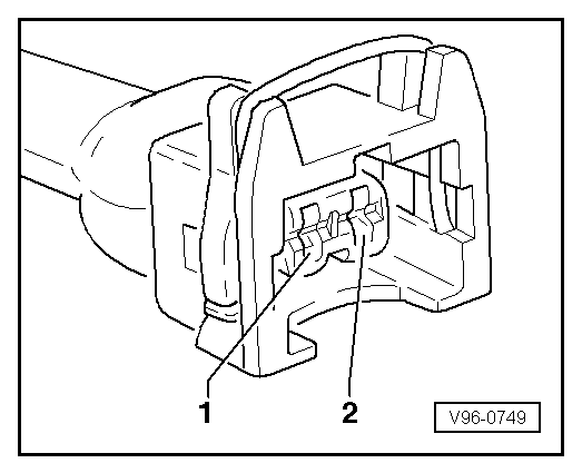
If no wiring fault is detected:

Check sensor:
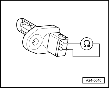
  • ‒ Unplug connector from intake air temperature sender.
 
A24-0040
  • ‒ → Connect multimeter to sender to measure resistance.

Specified values:

Temperature oC

Resistance kω

-20

approx. 13.8

0

approx. 5.5

20

approx. 2.4

40

approx. 1.1

60

approx. 0.6

Example:

If air temperature is between 0 oC and 20 oC, resistance must be between 5.5 kωand 2.4 kω .

If the specified value is not attained:

  • ‒ Replace intake air temperature sender.

Checking engine speed sender -G28 > < Checking ignition coils