
A4 Mk1
|
Checking ignition system
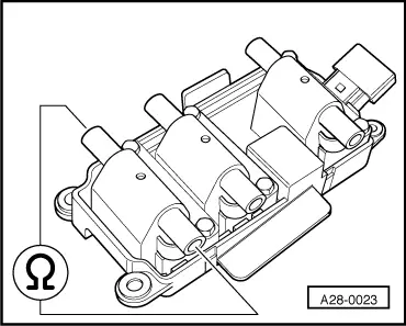
Checking ignition coils
|
 |
|
|
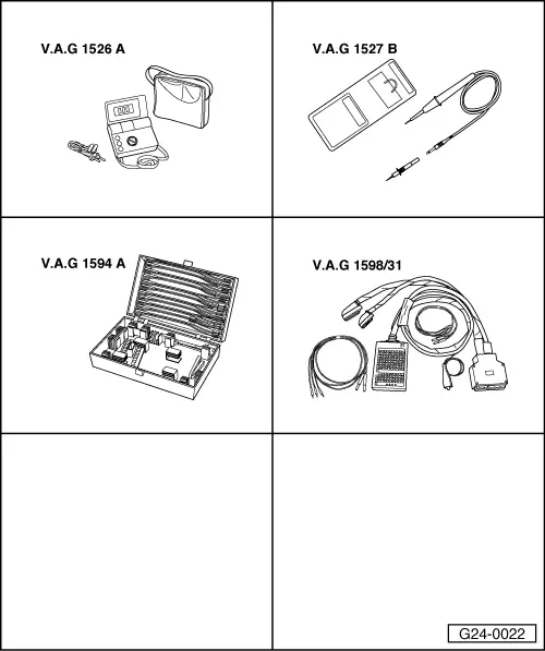
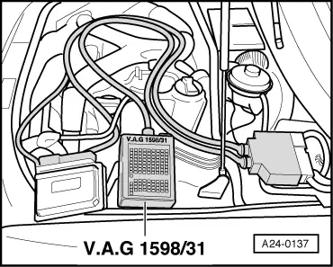
Special tools, testers and workshop equipment required
Installation position => Overview installation positions - Page 24-5 Notes:
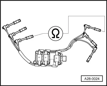
Checking ignition coils -N, -N128, and -N158
|
 |
|
|
 |
|||||
Specified values:
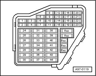
Checking earth supply of output stage |
 |
|||||
If the LED does not light up:
=> "Current Flow Diagrams, Electrical Fault Finding and Installation locations" binder
Checking voltage supply of ignition coils Note: Voltage supply to ignition coils is from fuel pump relay. |
 |
|
|
Test requirements:
|
|
||||||||
If the specified values are not attained:
|
 |
||||||||
If no wiring fault is detected:
|