audi Workshop Repair Guides

Audi Workshop Service and Repair Manuals

Checking data exchange between engine/ABS/gearbox control unit > < Checking brake light switch and brake pedal switch
Motronic fuel injection and ignition system (6 cyl.)
Checking auxiliary signals
Checking clutch pedal switch -F36
 
G24-0023

Special tools, testers and workshop equipment required

  • ◆ V.A.G 1526 A
  • ◆ V.A.G 1527 B
  • ◆ V.A.G 1594 A
  • ◆ V.A.G 1598/31
  • ◆ VAS 5051 with VAS 5051/1
  • or
  • ◆ V.A.G 1551 with V.A.G 1551/3 A

Note:

This signal prevents engine speed fluctuations and load change jolts when the clutch is disengaged. The signal is also required for the cruise control system.

Test sequence

  • ‒ Connect up vehicle diagnosis, measurement and information system VAS 5051 or fault reader V.A.G 1551 and select engine electronics control unit with "Address word" 01 .
    When doing this the ignition must be switched on.
 
→ Display readout:
Rapid data transfer    HELP
Select function XX
  • ‒ Enter "08" to select the function "Reading measured value block" and confirm entry with Q key.
 
→ Display readout:
Reading measured value block    Q
Enter display group number XXX
  • ‒ Enter "066" to select "Display Group 066" and confirm entry with the Q key.
 
→ Display readout:
Read measurement block 66    ⇒
    1    2    3    4
  • ‒ Check clutch pedal switch in display field 2.

Display zones

1

2

3

4

Display Group 066: Signals to engine control unit

Display

xxx km/h

XXXX

xxx km/h

XXXX

Display

ACTUAL speed

Switch settings

SPECIFIED speed

Switch settings

Range


X0XX
X1XX

Specified value

X0XX
(clutch pedal
not pressed)

X1XX
(clutch pedal
pressed)

Note:

Value:
X = no meaning

If the display is not as described:

Checking switch

  • ‒ Remove driver's storage compartment.

=> General body repairs - Interior; Repair group 68; Dash panel; Removing driver's shelf

  • ‒ Unplug the connector from clutch pedal switch.

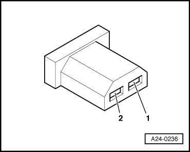
Note:

Receptacles are marked on back of plug.

  • ‒ Connect multimeter between contacts 1 and 2 to measure resistance.
    • ‒ Specified value: approx. 0 ω
  • ‒ Operate clutch pedal.
    • ‒ Specified value: ∞ ω (no continuity)

If the specified value is not attained:

  • ‒ Checking setting of switch or
  • ‒ Replace clutch pedal switch.

If the specified value is attained:

Checking voltage supply

 
A24-0236
  • ‒ → Connect voltage tester V.A.G 1527 B as follows:

Connector
Contact

Measure to

1

Car body earth point

  • ‒ Switch on the ignition.
    • ‒ The LED should light up.

If the LED does not light up:

  • ‒ Check the wiring between contact 1 of connector and fuse for open circuit/short to earth.

=> "Current Flow Diagrams, Electrical Fault Finding and Installation locations" binder

If the LED lights up:

Checking actuation

  • ‒ Connect the V.A.G 1598/31 test box to wiring harness leading to engine control unit; engine control unit should not be connected => Page 24-20.
 
A24-0236
  • ‒ → Check for open circuit and short to positive or earth in the following wiring connections:

Connector
Contact

Test box V.A.G 1598/31
Bush

2

39

  • ‒ Rectify any open/short as necessary.

Checking data exchange between engine/ABS/gearbox control unit > < Checking brake light switch and brake pedal switch