audi Workshop Repair Guides

Audi Workshop Service and Repair Manuals

Checking idling switch -F60 > < Checking ACF solenoid 1 -N80
MPI fuel injection and ignition system
Checking throttle valve potentiometer -G69
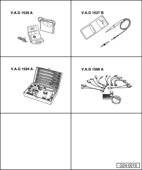
 
G24-0019

Special tools,
testers and equipment required

  • ◆ V.A.G 1526 A
  • ◆ V.A.G 1527 B
  • ◆ V.A.G 1594 A
  • ◆ V.A.G 1598 A
  • ◆ V.A.G 1598/11

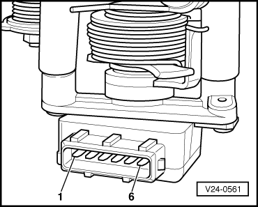
Fitting location => Fitting locations overview, Page 24-6

Notes:

  • ◆ The throttle valve potentiometer (G69) informs the engine control unit of the position of the throttle valve.
  • ◆ Checking operation=> Reading measured value block display group 002, Page 01-104.

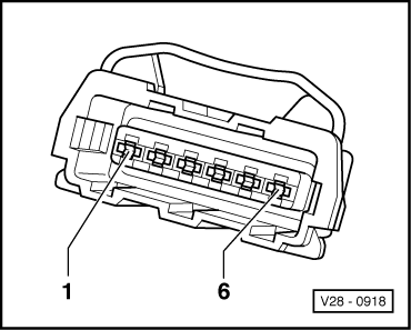
Checking internal resistance

  • ‒ Pull connector off throttle valve potentiometer.
 
V24-0561
  • ‒ → Connect multimeter between contacts 1 and 2 to measure resistance.
    • ‒ Specification: 1,5 ... 2.6 kω
  • ‒ Connect multimeter between contacts 2 and 3 to measure resistance.
    • ‒ Specification: 0,75 ... 1.3 kω
  • ‒ Slowly move the throttle valve lever to full throttle position.
    • ‒ Specification: Increasing resistance up to max. 3.6 kω

If a specification is not met:

  • ‒ Renew throttle valve potentiometer.
 
V28-0918

Checking power supply

  • ‒ Pull connector off throttle valve potentiometer.
  • ‒ Switch the ignition on.
  • ‒ → Connect multimeter between contacts 1 (positive) and 2 (earth) to measure voltage.
    • ‒ Specification: 4,5 ... 5.5 V
  • ‒ Connect multimeter between contacts 1 (positive) and 3 (signal) to measure voltage.
 
A87-0016
    • ‒ Specification: 4,5 ... 5.5 V

If a specification is not met:

  • ‒ → With the ignition switched off, use adapter V.A.G 1598/11 to connect test box V.A.G 1598 A to connector A only of engine control unit (control unit remains disconnected) .
 
V28-0918
  • ‒ → Check for open circuit and short to earth/positive or earth in the following wiring connections:

Connector
Contact

Test box V.A.G 1598 A
Socket

1

46

3

47

  • ‒ Rectify short circuit or open circuit if necessary.

=> "Current Flow Diagrams, Electrical Fault Finding and Fitting Locations" binder

Note:

Use only gold-plated contacts when repairing the contacts in the plug connectors for the knock sensors.

If no fault is detected in the wiring:

 
V28-0918
  • ‒ → Connect voltage tester V.A.G 1527 B as follows:

Connector
Contact

Measure against

2

Battery positive

    • ‒ The LED should light up.

If the LED does not light up:

  • ‒ Check wiring between contact 2 of connector and earth connection in wiring harness on right of engine compartment for open circuit and repair if necessary.

=> "Current Flow Diagrams, Electrical Fault Finding and Fitting Locations" binder

Note:

Use only gold-plated contacts when repairing the contacts in the plug connectors for the knock sensors.

  • ‒ If the wiring is OK, fit a new engine control unit => Page 24-20.

Checking idling switch -F60 > < Checking ACF solenoid 1 -N80