-
‒ Observe display in display zone 2.
|
|
|---|
|
|
Display zones
|
|
|
1
|
2
|
3
|
4
|
|
Display Group 66: Signals to engine control unit with ignition on
|
|
Display
|
xxx km/h
|
1 0 0 0
|
xxx km/h
|
1 0 0 0
|
|
Indicates
|
Actual speed
|
Switch positions
|
Specified speed
|
Switch positions for cruise control system
|
|
Range
|
|
off = 0
on = 1
|
|
off = 0
on = 1
|
|
Specification
|
|
1 0 0 0
|
|
|
|
Note
|
|
Relevance of figures
|
|
|
Relevance of figures in 4-digit readout in display zone 2
|
|
|---|
|
x
|
x
|
x
|
x
|
Display zone 2
|
|
|
|
|
X
|
Brake light switch
0 = Brake pedal not depressed
1 = Brake pedal depressed
|
|
|
|
X
|
|
Brake pedal switch
0 = Brake pedal not depressed
1 = Brake pedal depressed
|
|
|
X
|
|
|
Clutch pedal switch
0 = Clutch pedal not depressed
1 = Clutch pedal depressed
|
|
X
|
|
|
|
Cruise control system (CCS)
0 = CCS deactivated
1 = CCS enabled
|
|
|
|---|
|
|
Display zones
|
|
|
1
|
2
|
3
|
4
|
|
Display Group 66: Signals to engine control unit
|
|
Display
|
xxx km/h
|
1 0 1 1
|
xxx km/h
|
0 0 0 0
|
|
Indicates
|
Actual speed
|
Switch positions
|
Specified speed
|
Switch positions for cruise control system
|
|
Range
|
|
off = 0
on = 1
|
|
off = 0
on = 1
|
|
Specification
|
|
1 0 1 1
|
|
|
|
Note
|
|
Both readouts must change from 0 to 1.
|
|
|
-
‒ Allow brake pedal to return slowly to its normal position.
-
‒ Both readouts should return from 1 to 0.
If one or both of the readouts does not change:
-
‒ Test voltage supply
=> Page 24-186.
Testing voltage supply
-
‒ Remove storage compartment on driver's side.
=> General body repairs, Interior; Repair group 68; Dash panel; Removing driver's storage compartment
-
‒ Unplug 4-pin connector on brake pedal.
-
‒ Connect hand-held multimeter (voltage range) between the following sockets on the connector:
-
‒ Switch ignition off.
|
|
|---|
|
4-pin connector on
wiring harness, socket
|
Specification
|
|
1 + earth
|
Battery voltage
|
|
4-pin connector on
wiring harness, socket
|
Specification
|
|
3 + earth
|
Battery voltage
|
If specifications are met:
-
‒ Test wiring connections => Page 24-186.
If specifications are not met:
-
‒ Test wiring connections from sockets 1 and 3 of connector for open circuit or short to earth.
=> Current flow diagrams, Electrical fault finding and fitting locations binder
-
‒ Rectify any open/short circuit as necessary.
Checking wiring connections
-
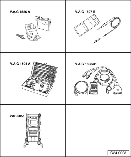
‒ Connect test box V.A.G 1598/31 to wiring harness for engine control unit. Do not connect to the engine control unit itself.
=> Page 24-26.
Test the following wiring connections for open circuits and short to positive or earth:
|
|
|---|
|
4-pin connector on
wiring harness, socket
|
Test box V.A.G 1598/31, socket
|
|
2
|
53
|
|
4
|
63
|
Resistance in wiring: max. 1.5 Ohm
-
‒ Rectify any open/short circuit as necessary.
=> Current flow diagrams, Electrical fault finding and fitting locations binder
If no open circuits are found in wiring:
-
‒ Renew brake light switch / brake pedal switch.
|