audi Workshop Repair Guides

Audi Workshop Service and Repair Manuals

Testing auxiliary signals > < Checking intake manifold temperature sender
TDI diesel injection and glow plug system (4-cyl.) 08.99 ä
Checking control unit input values
Checking modulating piston movement sender -G149 and quantity adjuster -N146

The metering unit (quantity adjuster) is an electromagnetic swivelling positioner which is controlled by the control unit via a directed duty cycle (on-off ratio). The eccentric shaft on the metering unit moves the modulating piston on the high pressure piston and thereby regulates the quantity of fuel injected.

The modulating piston movement sender informs the control unit of the position of the modulating piston, thereby indicating the quantity of fuel injected.

  • ‒ Read measured value block, Display Group 01, engine at idling speed
 
→ Indicated on display:
Read measured value block 1    "
    840 rpm    5.6 mg/H    1.480 V    87.3 5C
  • ‒ Check display in display zone 4 (coolant temperature).
 
→ Specification: At least 85 °C
Read measured value block 1    "
    840 rpm    5.6 mg/H    1.480 V    87.3 5C

Continue with check when coolant temperature is attained.

  • ‒ Switch off any electrical consumers that may be on (air conditioner, rear window heater, lights etc.).
  • ‒ Check display in display zone 3 (voltage supplied from modulating piston movement sender).
 
→ Specification: 1.250...1.700 V
Read measured value block 1    "
    840 rpm    5.6 mg/H    1.480 V    87.3 5C

If the specification is not obtained:

  • ‒ Replace injection pump.

Electrical check of modulating piston movement sender (G149) and quantity adjuster (N146)

 
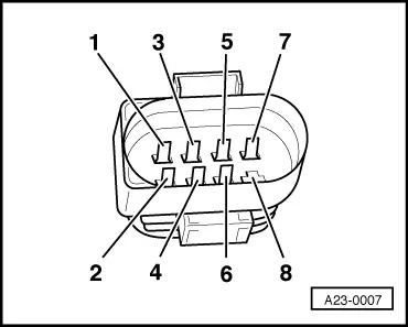
A23-0007
  • ‒ Switch off ignition.
  • ‒ Disconnect connector for sender=>Fitting locations overview, Page 23-4.
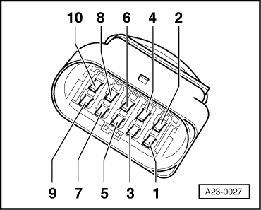
  • ‒ Connect hand-held multimeter (resistance test range) between the following contacts on the injection pump connector:

→ Testing wiring connections on vehicles with 8-pin connector.

 
A23-0027

→ Testing wiring connections on vehicles with 10-pin connector.

8-pin or 10-pin injection pump connector

Specification

1 + 2

4.9...7.5 ω

3 + 2

4.9...7.5 ω

6 + 5

0.4...1.1 ω

If the specifications are not obtained:

  • ‒ Replace injection pump.

Testing current supply and wiring connections

  • ‒ Switch off ignition.
  • ‒ Disconnect connector for sender=>Fitting locations overview, Page 23-4.
  • ‒ Switch ignition on.
 
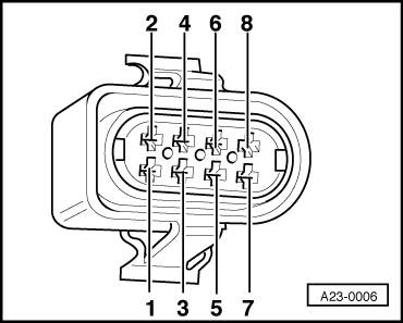
A23-0006
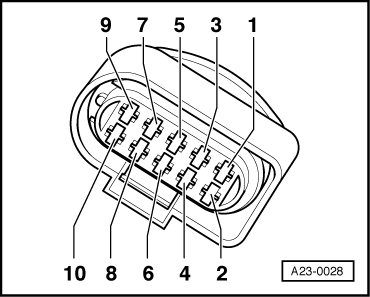
  • ‒ Connect hand-held multimeter (voltage test range) between the following contacts on the wiring harness connector:

→ Measuring voltage on vehicles with 8-pin connector.

 
A23-0028

→ Measuring voltage on vehicles with 10-pin connector.

8-pin or 10-pin connector on wiring harness, contact

Specification

1 + earth

approx. 2.5 V

3 + earth

approx. 2.5 V

5 + earth

approx. battery voltage

If the specifications are not obtained:

  • ‒ Connect test box V.A.G 1598/31 to wiring harness for engine control unit. Do not connect to the engine control unit itself.
    => Page 23-47.
 
A23-0006

The following wiring connections are to be checked for open circuits and/or short to positive or negative.

→ Testing wiring connections on vehicles with 8-pin connector.

 
A23-0028

→ Testing wiring connections on vehicles with 10-pin connector.

8-pin or 10-pin connector on wiring harness, contact

Test box V.A.G 1598/31, socket

1

108

2

106

3

99

5

1 and 2

6

116 and 121

  • ‒ Rectify any open/short circuit as necessary.

Testing auxiliary signals > < Checking intake manifold temperature sender