audi Workshop Repair Guides

Audi Workshop Service and Repair Manuals

Dynamically checking and adjusting commencement of injection: engine code AHH > < Dynamically checking and adjusting commencement of injection: Engine codes: AFF, AHU, AFN
TDI Injection and Glow Plug System (4-cyl.) 07.97 > 07.99
Servicing diesel direct injection system
Removing and installing the injection pump Engine code: AHH

Remove the injection pump

  • ‒ Move lock carrier to service position.

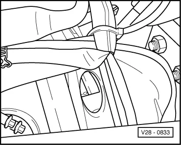
=> General Body Assembly, Exterior; Repair group 50; Body front; Lock carrier-service position

  • ‒ Remove the upper toothed belt guard and the cylinder head cover.
  • ‒ Set the crankshaft to TDC for cylinder No. 1.
 
V28-0833

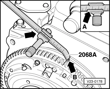
TDC-position of the crankshaft in vehicles with automatic gearboxes =>Page 23-39.

TDC-position of the crankshaft in vehicles with manual gearboxes

  • → The -0- mark should be below the edge visible through the inspection hole.

With engine removed

 
V23-0178
  • ‒ → Screw in the adjustment device 2068 A as shown.
  • ‒ Set the adjusting device to 107 mm. The left notch on the vernier scale is the reference point.
  • ‒ Turn the crankshaft until the TDC marking on the fly wheel is in alignment with the end of the setting device -arrow-.

 
V13-1151
  • ‒ → Lock the camshaft with the setting bar.
  • ‒ Centre the setting bar as follows:
    Turn locked camshaft so that one end of setting bar contacts the cylinder head. Measure the gap at the other end of the setting bar using a feeler gauge. Place a feeler gauge corresponding to half the gap between the setting bar and the cylinder head. Turn camshaft until the setting bar contacts the feeler gauge. Insert a 2nd feeler gauge of the same thickness at the other end, between the setting bar the and cylinder head.
 
A23-0044
  • ‒ → Loosen injection pump sprocket attachment screws -1-.
  • ‒ Remove the nuts from the tensioning roller.
  • ‒ Remove toothed belt from camshaft and injection pump sprockets.

=> Repair group 13; Dismantling and assembling engine; Removing and installing toothed belt and adjusting tension

  • ‒ Unscrew the injection pipes from pump using the slotted ring spanner 3035.
  • ‒ Cover openings with a clean cloth.
 
A23-0042
  • ‒ → Unscrew the securing bolts from the console -1-.

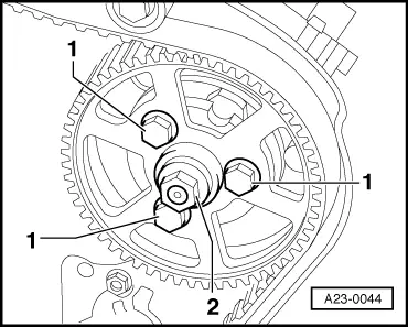
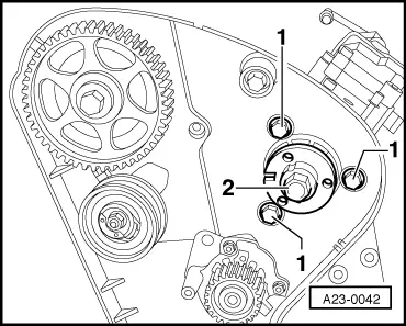
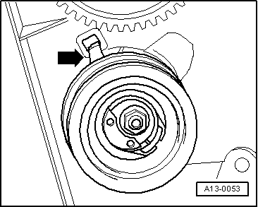
Note:

Do not loosen hub nut -2-. Otherwise the injection pump basic setting is maladjusted and cannot be corrected using workshop tools.

 
V23-0301
  • ‒ → Then remove securing bolt from rear support (arrow).
  • ‒ Remove injection pump.

Installing the injection pump

  • ‒ Insert the injection pump into the console and then first tighten the securing bolt on the rear support with the conical nut.
  • ‒ Insert front securing bolts and tighten to 25 Nm.
  • ‒ Fit the injection pump sprocket loosely to the hub using new securing bolts.
  • ‒ Centre the injection pump sprocket in the slots.
 
A13-0052
  • ‒ → Lock the injection pump sprocket with pin 3359.
  • ‒ Loosen the securing bolt in the camshaft gear wheel by1/2 a turn.

 
V13-0897
  • ‒ → Insert a drift through the hole in the rear of the toothed belt guard and release the camshaft gear wheel from the camshaft taper by tapping with a hammer.
  • ‒ Check whether TDC mark on flywheel and the reference mark line up.
  • ‒ Place the toothed belt on the injection pump sprocket and the tensioning roller.
 
N13-0027
  • ‒ → Tension the toothed belt. For this purpose, rotate spanner (e.g. Matra V159) on eccentric clockwise until the notch and the raised arrows line up.

 
A13-0053

Note:

→ Make sure that the holding claw is correctly positioned.

  • ‒ Tighten securing nut to 20 Nm.
  • ‒ Check TDC mark on flywheel again.
  • ‒ Tighten the new securing bolts for the injection pump sprocket to 20 Nm.

Notes:

  • ◆ After the injection start dynamic test, screws 1/4 must be tightened by a (90°) turn.
  • ◆ The securing bolts are stretch bolts and can therefore only be used once.
  • ‒ Tighten camshaft sprocket securing bolt to 45 Nm.
  • ‒ Remove the locking pin 3359.
  • ‒ Remove the setting bar 2065 A from the camshaft.
 
A20-0338
  • ‒ Turn the crankshaft two rotations in the engine direction of rotation until the crankshaft is set to the TDC for cylinder No. 1 again.
  • ‒ Reconnect injection pipes, fuel supply pipe and electrical wiring.

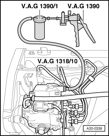
→ Fill injection pump with clean diesel fuel as follows:

    • ‒ Screw pipe union 1318/10 into the return pipe connection on the injection pump.
    • ‒ Connect the vacuum hand pump 1390 with the bleeder vessel V.A.G 1390/1 to the return pipe connection.
    • ‒ Operate vacuum hand pump until fuel comes out of return pipe connection. Do not draw fuel into the vacuum pump.
  • ‒ Connect return pipe.
  • ‒ Install the cylinder head cover and intake hose.
  • ‒ Dynamically checking and adjusting commencement of injection =>Page 23-34.

Dynamically checking and adjusting commencement of injection: engine code AHH > < Dynamically checking and adjusting commencement of injection: Engine codes: AFF, AHU, AFN