|
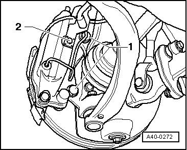
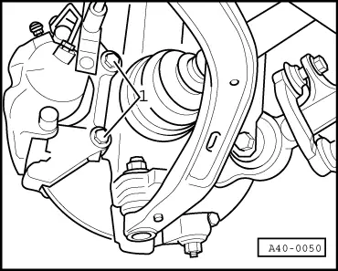
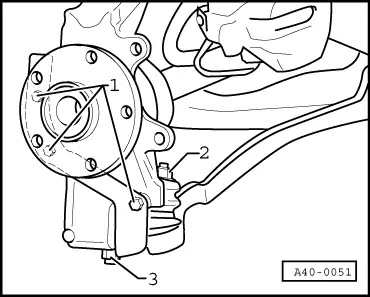
Wheel bearing housing
Removing and installing wheel bearing housing
Special tools and workshop equipment required
-
◆ V.A.G 1332 Torque wrench
-
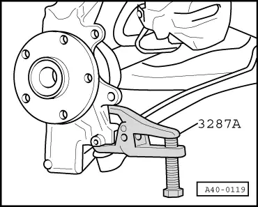
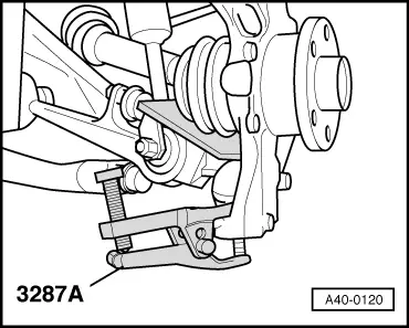
◆ 3287A Ball joint puller
Different wheel bearing housing versions with and without bushings
Wheel bearing housings with bushings are being introduced as of Model Year 2002 to provide optimum sealing of lower link bushes (track control link and guide link).
-
◆ Assignment => Parts List
-
‒ Wheel bearing housings with no bushings (old version) for wheel bearing ø 75 mm and ø 82 mm
-
‒ Wheel bearing housings with bushings (new version) for wheel bearing ø 75 mm and ø 82 mm
-
◆ A combination of wheel bearing housings with and without bushings is permitted.
-
◆ When installing wheel bearing housings with bushings, use is also to be made of the corresponding track control links (new type) and track control link/guide link fastening elements.
- Flange nuts are to be replaced by combi nuts as fastening elements.
- Guide links need not be replaced.
-
◆ Conventional flange nuts are to be fitted for vehicles with wheel bearing housings with no bushings and old type track control links.
-
◆ Bushings are not intended to be replaced. If damaged, replace wheel bearing housing.
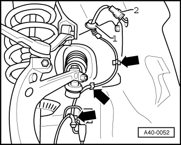
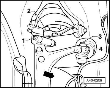
Removing
|