-
‒ Invoking customer service software .
-
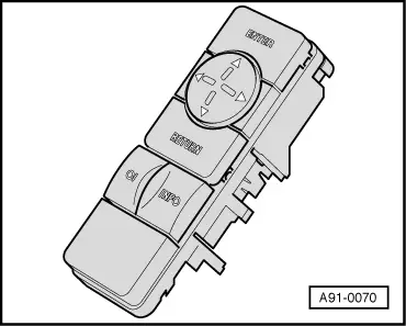
‒ → Select the menu item "WIRING" with the cursor keys.
Display:
|
|
|
|
SERV. MENU:
SET WHLS
> WIRING
DRIVE TST
SYS. TEST
END
|
|
-
‒ A test of the electrical connections is started with the "ENTER" key in service.
Display:
|
CHECK:
A4 - SAL - B5
TYRE:
205/60 15
|
|
|
> YES
NO
|
|
-
‒ If the selection is confirmed with the "ENTER" key, the program continues with the relevant menu item.
-
‒ If the selection is not confirmed with the "ENTER" key, the following instruction appears:
Display:
|
CARRY OUT
WHEEL
CALIBRATION!
|
|
|
> OK
|
|
-
‒ Confirm the display OK with the "ENTER" key.
Display:
The GPS aerial and compass pickups are tested and checked whilst the "PLEASE WAIT" screen is displayed.
The following display appears if a fault is found in the GPS aerial:
|
|
|
|
NO SIGNALS
FROM GPS
AERIAL!
> CONTINUE
|
|
-
‒ Press "ENTER" key to continue.
-
‒ Check the fault in the wiring/from incorrect location selection and if necessary repair, either immediately or at the end of the wiring test when all faults are displayed once again
.
The following display appears if a fault occurs in the compass:
|
|
|
|
NO
COMPASS-
SIGNALS!
> CONTINUE
|
|
-
‒ Press "ENTER" key to continue.
-
‒ Immediately check he fault in the wiring/from incorrect location selection and if necessary repair, either immediately or at the end of the wiring test when all faults are displayed once again .
Next display:
-
‒ Switch on rear window heating and confirm with the "ENTER" key.
Display:
|
|
|
|
REAR
WINDOW
HEATING
OFF!
> OK
|
|
-
‒ Switch off rear window heating and confirm with the "ENTER" key.
However, if the following display appears, a fault has been detected in the shunt resistor or voltage tap:
|
|
|
|
NO REAR
WINDOW-
READING.
CHECK
PLUG!
> CONTINUE
|
|
Switch for heated rear window has not been actuated or
-
‒ wiring to rear window heating is not OK.
-
‒ Press "ENTER" key to continue.
-
‒ Check the fault in the wiring/on the connectors and if necessary repair, either immediately or at the end of the wiring test when all faults are displayed once again
.
Notes:
-
◆ A shunt resistor has been installed in the A4 Saloon.
-
◆ A voltage tap has been installed at the rear window of the A4 Avant, i.e. the battery voltage is measured.
Display:
|
|
|
|
DRIVE AT
CONSTANT
SPEED AND
COMPARE
> CONTINUE
|
|
-
‒ Press "ENTER" key to continue.
Display:
|
|
|
|
BOTH WHEEL
SPEEDS
WITH
SPEEDOMETER
> OK
|
|
-
‒ Confirm the display OK with the "ENTER" key.
Display:
-
‒ Start the engine and drive forwards straight ahead. Compare the displays of both L and R wheel sensors.
-
‒ Stop the vehicle.
-
‒ If the values are within the permissible lower speed range (the difference must not be more than 5 km/h), use the "ENTER" key to confirm the display > YES, otherwise select > NO.
-
‒ Check the fault in the wiring/wheel calibration and if necessary repair, either immediately or at the end of the wiring test when all faults are displayed once again .
Display:
-
‒ Engage reverse gear.
-
‒ Reverse the vehicle approx. 3 m and stop.
-
‒ Confirm the display OK with the "ENTER" key.
-
‒ Check the fault in the wiring/wheel calibration and if necessary repair, either immediately or at the end of the wiring test when all faults are displayed once again.
.
If no faults are detected in the wiring test, the following display appears:
Display:
-
‒ Confirm the display with the "ENTER" key to jump to the main menu. The next commissioning step DRIVE TST is then activated.
Display:
|
|
|
|
SERV. MENU:
SET WHLS
WIRING
> DRIVE TST
SYS. TEST
END
|
|
-
‒ Press "ENTER" key to start the TEST DRIVE
.
Several faults can be recognised in the wiring test in extreme cases.
Notes:
-
◆ Fault determination is based on the assessment of signals from the corresponding sensors. A defective sensor can also be the cause of the error in addition to a wiring error.
This options should only be taken into consideration after ensuring that the wiring is correctly installed (see current flow plan).
-
◆ Fault areas can also be checked individually via the SYS. TEST menu, before e.g. the complete wiring test is performed after repair measures by clearing the menu item DRIVE TST.
Possible display:
|
|
|
|
ERROR:
GPS
COMPASS
SHUNT
WH. SENSOR
REV. GEAR
|
|
Note:
REAR VOLT. may also be displayed for SHUNT
-
‒ Rectify any faults by taking appropriate measures.
-
‒ Confirm the display with the "ENTER" key to jump to the main menu.
Display:
|
|
|
|
SERV. MENU:
SET WHLS
> WIRING
DRIVE TST
SYS. TEST
END
|
|
-
‒ Select the menu item "WIRING" once again with the cursor keys.
-
‒ Confirm the display with the "ENTER" key to repeat the electrical connections test in service.
|