
A4 Mk2
|
|
|
|
|
|
|

| 1 - | 24 Nm |
| q | Apply locking fluid when fitting |
| q | Locking fluid → Parts catalogue |
| 2 - | 4 Nm |
| 3 - | Seat longitudinal adjustment handle |
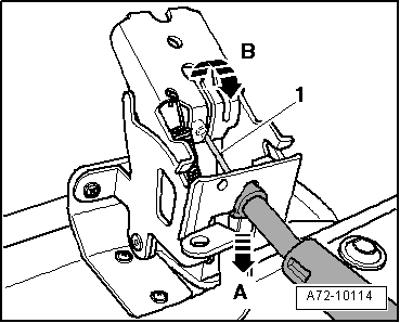
| q | Detach operating cable for seat longitudinal adjustment → Fig. |
| 4 - | 24 Nm |
| q | Apply locking fluid when fitting |
| q | Locking fluid → Parts catalogue |
| 5 - | Seat pan |
| Removing |
| – | Remove seat → Chapter. |
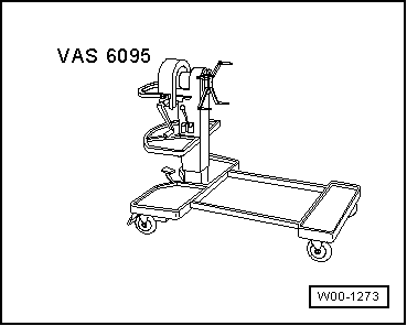
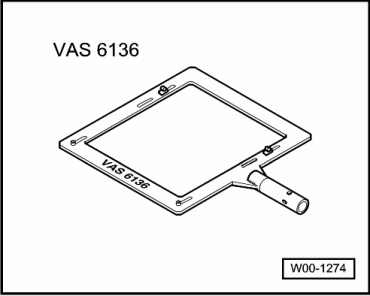
| – | Attach seat repair stand -VAS 6136- to engine and gearbox support -VAS 6095-. |
| – | Attach front seat to seat repair stand -VAS 6136-. |
| – | Remove side trim (sill side) → Chapter. |
| – | Remove side trim (tunnel side) → Chapter. |
| – | Remove control unit → Chapter. |
| Vehicles up to 04.2006: |
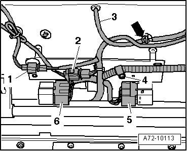
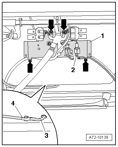
| – | Detach relay sockets from metal bracket → Fig.. |
| Vehicles from 05.2006 onwards: |
| – | Use a Ø 4.0 mm bit to drill out pop rivets and detach retaining plate for relay socket and wiring harness → Fig.. |
| – | Unplug electrical connector for seat heating → Fig.. |
| All vehicles (continued): |
| – | Disconnect pneumatic hose → Fig.. |
| – | Move electrical wiring clear → Fig.. |
| – | Detach operating cable for seat longitudinal adjustment from release lever → Fig.. |
| – | Unscrew bolts -1-, -4- and -11-. |
| – | Remove bolts -6- and -8- and set down backrest behind seat pan. |
| – | Remove seat pan. |
| Installing |
| Installation is carried out in the reverse order; note the following: |
| – | Apply locking fluid when fitting bolts (locking fluid → Parts catalogue). |
| 6 - | 20 Nm |
| q | Apply locking fluid when fitting |
| q | Locking fluid → Parts catalogue |
| 7 - | Backrest |
| Removing |
| – | Remove seat → Chapter. |
| – | Attach seat repair stand -VAS 6136- to engine and gearbox support -VAS 6095-. |
| – | Attach front seat to seat repair stand -VAS 6136-. |
| – | Remove side trim (sill side) → Chapter. |
| – | Remove side trim (tunnel side) → Chapter. |
| – | Remove control unit → Chapter. |
| – | Detach relay sockets from metal bracket → Fig.. |
| – | Disconnect pneumatic hose → Fig.. |
| – | Move electrical wiring clear → Fig.. |
| – | Remove bolt -2- and remove lever for seat longitudinal adjustment -3-. |
| – | Detach operating cable for seat longitudinal adjustment from release lever → Fig.. |
| Vehicles from 05.2006 onwards: |
| – | Disengaging release lever for seat rails → Chapter |
| All vehicles (continued): |
| – | Unscrew bolts -1-, -4- and -11-. |
| – | Remove seat pan -5-. |
| – | Remove bolts -6- and -8-. |
| – | Detach backrest and remove wiring harness from seat frame. |
| Installing |
| Installation is carried out in the reverse order; note the following: |
| – | Apply locking fluid when fitting bolts (locking fluid → Parts catalogue). |
| 8 - | 20 Nm |
| q | Apply locking fluid when fitting |
| q | Locking fluid → Parts catalogue |
| 9 - | Pneumatic hose |
| q | For flaps for backrest bolster adjustment |
| 10 - | Electrical wiring harness |
| 11 - | 24 Nm |
| q | Apply locking fluid when fitting |
| q | Locking fluid → Parts catalogue |
| 12 - | Seat frame |
|
|
|
|