
A4 Mk2
| Dismantling and assembling input shaft |
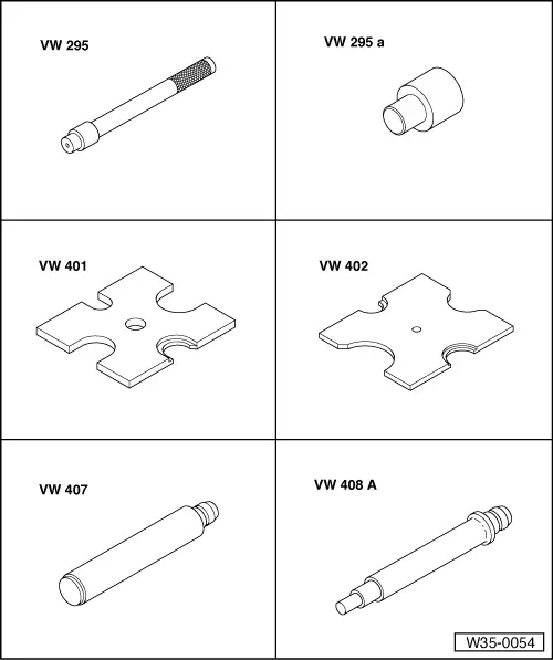
| Special tools and workshop equipment required |
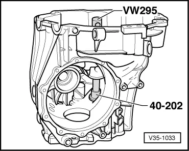
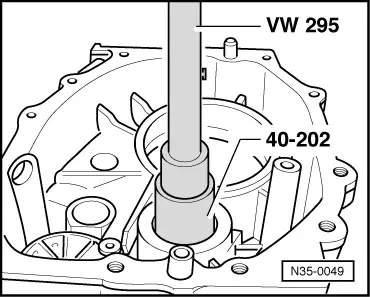
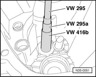
| t | Drift -VW 295- |
| t | Adapter -VW 295 A- |
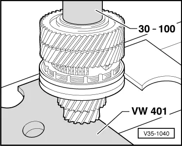
| t | Thrust plate -VW 401- |
| t | Thrust plate -VW 402- |
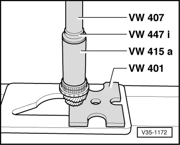
| t | Press tool -VW 407- |
| t | Press tool -VW 408 A- |
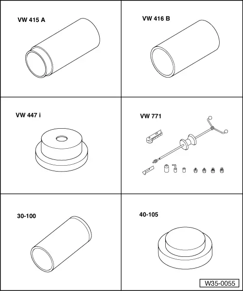
| t | Tube -VW 415 A- |
| t | Tube -VW 416 B- |
| t | Thrust plate -VW 447 i- |
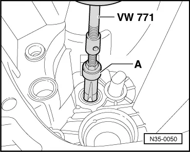
| t | Multi-purpose tool -VW 771- |
| t | Drift sleeve -30 - 100- |
| t | Thrust plate -40 - 105- |
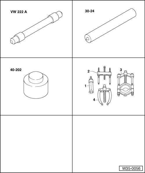
| t | Drift -VW 222 A- |
| t | Drift -30 - 24- |
| t | Extractor -40 - 202- |
| t | -1-Internal puller -Kukko 21/4- |
| t | -3-Splitter -Kukko 17/2- |
 Note
Note| t | When installing new gear wheels or input shaft, consult technical data → Chapter. |
| t | The position of tapered roller bearings is affected when renewing ball bearing, gearbox housing or input shaft. In this case the input shaft must be re-adjusted → Chapter. |
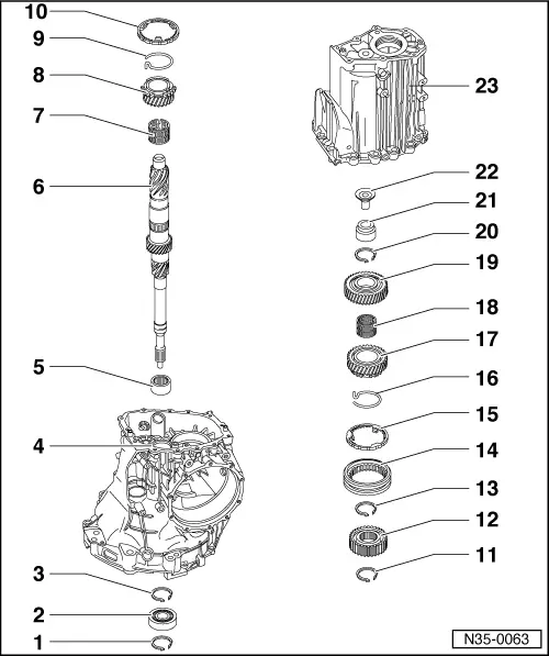
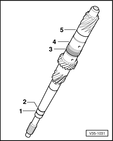
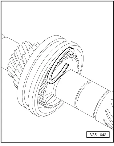
| 1 - | Circlip |
| q | Mark |
| q | Installation position → Fig. |
| q | Determining thickness → Chapter |
| 2 - | Ball bearing |
| q | Removing and installing → Chapter |
| 3 - | Circlip |
| q | Mark |
| q | Installation position → Fig. |
| q | Determining thickness → Chapter |
| 4 - | Gearbox housing |
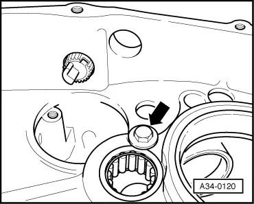
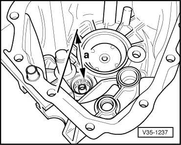
| 5 - | Needle bearing |
| q | Secured with bolt on some gearboxes → Fig. |
| q | Driving out → Fig. |
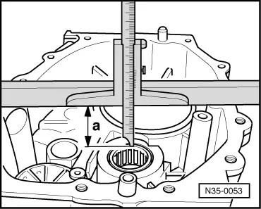
| q | Installation position → Fig. |
| q | Pressing in → Fig. |
| q | Securing → Fig. |
| 6 - | Input shaft |
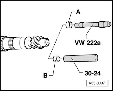
| q | With oil feed sleeve |
| q | Knocking in oil feed sleeve → Fig. |
| q | Adjusting → Chapter |
| 7 - | Needle bearing for 3rd gear |
| 8 - | 3rd speed selector gear |
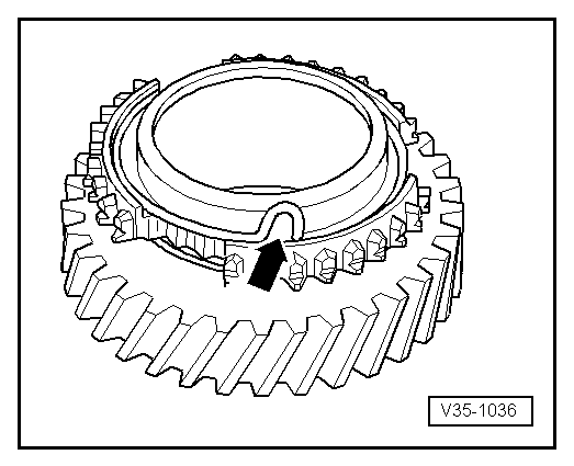
| 9 - | Spring |
| q | Insert in 3rd speed selector gear → Fig. |
| q | Allocation to selector gear → Electronic parts catalogue |
| 10 - | Synchro-ring for 3rd gear |
| q | Checking for wear → Fig. |
| 11 - | Circlip |
| q | Mark |
| q | Installation position → Fig. |
| 12 - | Synchronising hub for 3rd and 4th gear |
| q | Higher shoulder faces towards 3rd gear |
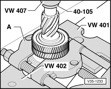
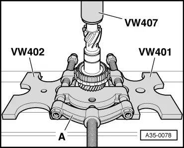
| q | Pressing off → Fig. |
| q | Pressing on → Fig. |
| 13 - | Circlip |
| q | Mark |
| q | Installation position → Fig. |
| q | Redetermine thickness if synchronising hub is replaced → Fig. |
| 14 - | Locking collar for 3rd and 4th gear |
| q | Installation position → Fig. |
| 15 - | Synchro-ring for 4th gear |
| q | Checking for wear → Fig. |
| 16 - | Spring |
| q | Insert in 4th speed selector gear → Fig. |
| q | Allocation to selector gear → Electronic parts catalogue |
| 17 - | 4th speed selector gear |
| 18 - | Needle bearing for 4th gear |
| 19 - | 5th gear wheel |
| q | Pressing off → Fig. |
| q | Pressing on → Fig. |
| 20 - | Circlip |
| q | Mark |
| q | Installation position → Fig. |
| q | If the 5th gear wheel is renewed redetermine thickness → Fig. |
| 21 - | Roller bearing |
| q | Renew |
| q | Will be damaged during removal |
| q | Pulling out → Fig. |
| q | Installation position → Fig. |
| q | Driving in → Fig. |
| 22 - | Sleeve |
| q | Made of plastic |
| 23 - | Gearbox cover |
Note
|
|
|
|
|
|
|
|
|
|
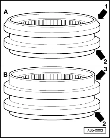
| Item | Oil feed sleeve dia. | Fitting tool |
| A | 14 mm | Drift -VW 222 A- |
| B | 16 mm | Drift -30 - 24- |
|
|
|
|
|
|
|
|
|
|
|
|
|
|

|
|
|
|
|
| Circlip thickness (mm) | ||
| 1.90 | 1.96 | 2.02 |
| 1.93 | 1.99 | 2.05 |
|
| Circlip thickness (mm) | ||
| 1.90 | 1.96 | 2.02 |
| 1.93 | 1.99 | |
|
|
|
|
|
|
 WARNING