
A4 Mk2
| Dismantling and assembling pinion shaft and hollow shaft |
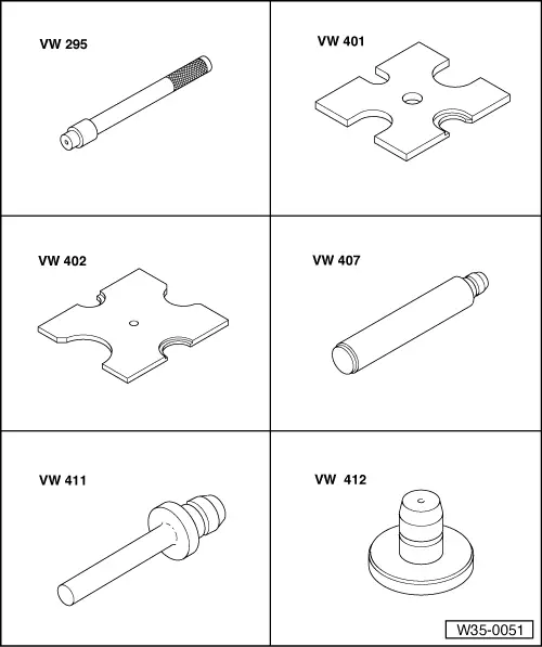
| Special tools and workshop equipment required |
| t | Drift -VW 295- |
| t | Thrust plate -VW 401- |
| t | Thrust plate -VW 402- |
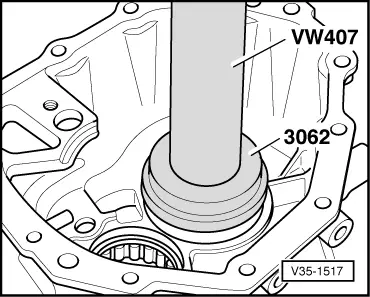
| t | Press tool -VW 407- |
| t | Press tool -VW 411- |
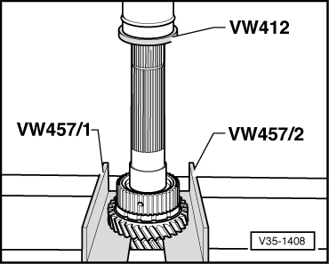
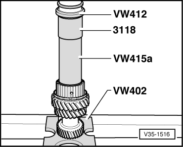
| t | Press tool -VW 412- |
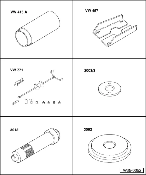
| t | Tube -VW 415 A- |
| t | Support rails -VW 457- |
| t | Multi-purpose tool -VW 771- |
| t | Installing ring -2003/3- |
| t | Punch -3013- |
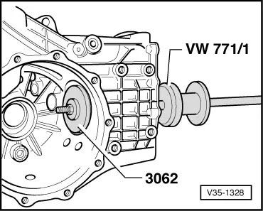
| t | Thrust pad -3062- |
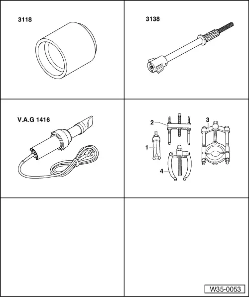
| t | Press tool -3118- |
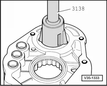
| t | Drift -3138- |
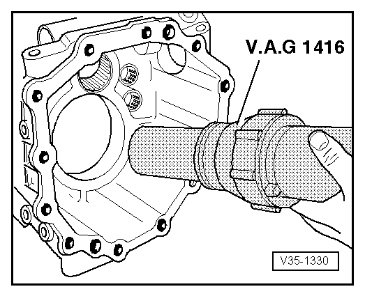
| t | Hot air blower -V.A.G 1416- |
| t | -1-Internal puller -Kukko 21/1- |
| t | -3-Splitter -Kukko 17/2- |
| Exploded view |
 Note
Note| t | When installing new gears or final drive gear set → Chapter „Code letters, allocation, transmission ratios, capacities“. |
| t | Adjustment work is required when renewing the parts marked with 1) → Anchor. |
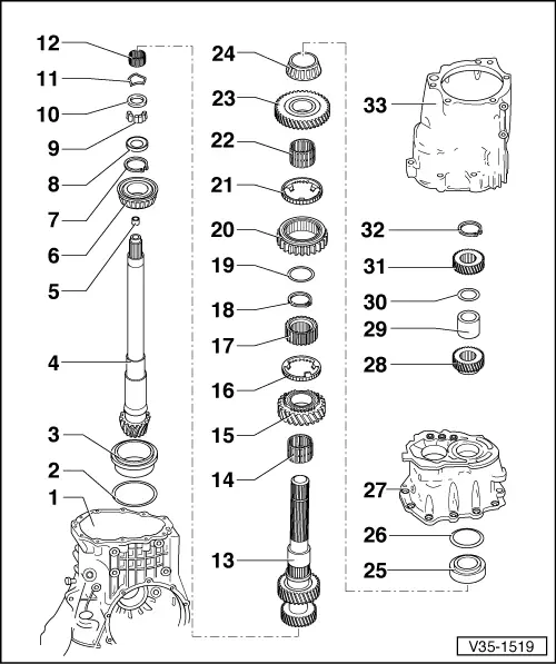
| 1 - | Gearbox housing |
| q | Servicing → Chapter |
| 2 - | Shim “S3” |
| q | Table of adjustments → Anchor |
| 3 - | Outer race for large tapered roller bearing 1) |
| q | Pulling out → Fig. |
| q | Pressing in → Fig. and → Fig. |
| 4 - | Pinion shaft 1) |
| q | Paired with crown wheel (final drive gear set) |
| q | Adjusting pinion shaft and crown wheel → Chapter |
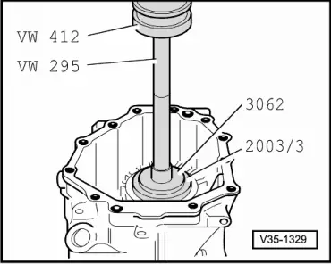
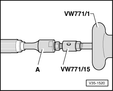
| 5 - | Needle roller bearing for flange shaft/pinion shaft |
| q | Pulling out → Fig. |
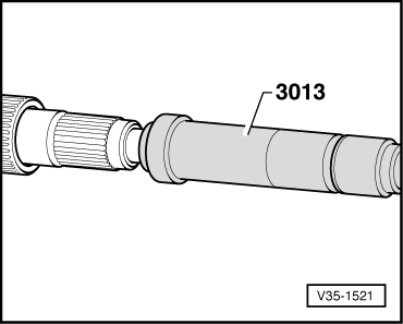
| q | Driving in → Fig. |
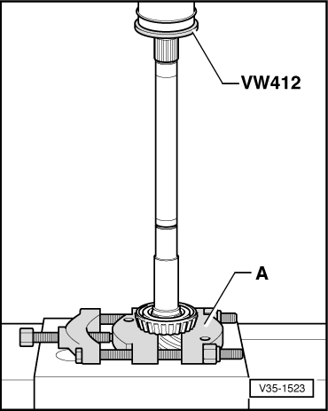
| 6 - | Inner race for large tapered roller bearing 1) |
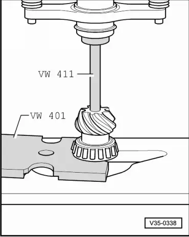
| q | Pressing off → Fig. |
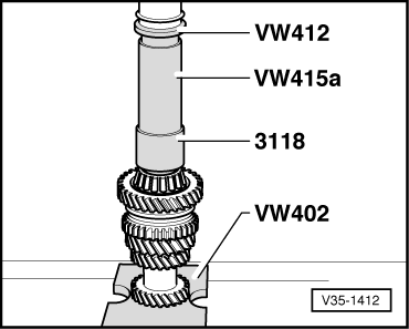
| q | Pressing on → Fig. |
| q | Low-friction bearing; do not oil bearing when measuring friction torque |
| 7 - | Circlip |
| q | Re-determining thickness → Fig. |
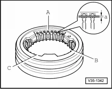
| 8 - | Flange ring |
| q | Installation position → Anchor |
| 9 - | Tapered rollers |
| q | 23 x |
| q | Installation position → Anchor |
| 10 - | Support ring |
| q | Installation position → Anchor |
| 11 - | Corrugated spring |
| 12 - | Needle bearing for pinion shaft/hollow shaft |
| q | Lubricate with gear oil before installing |
| 13 - | Hollow shaft with 3rd and 4th gear wheels 1) |
| 14 - | Needle bearing for 2nd speed selector gear |
| q | Split |
| q | Lubricate with gear oil before installing |
| 15 - | 2nd speed selector gear |
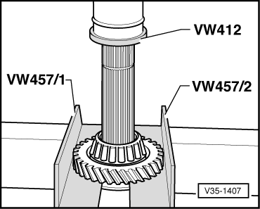
| q | Pressing off → Fig. |
| q | Before installing, fit spring and slide needle bearing onto hollow shaft |
| q | After installing, check axial clearance with a feeler gauge (0.15 ... 0.35 mm) |
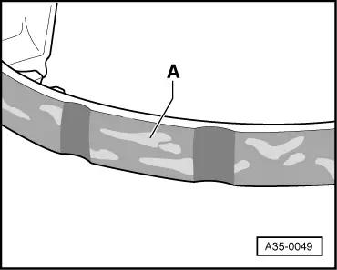
| 16 - | Synchro-ring for 2nd gear |
| q | With molybdenum coating |
| q | Checking for wear → Fig. |
| 17 - | Synchronising hub for 1st and 2nd gear |
| q | Pressing off → Fig. |
| q | Pressing on → Fig. |
| q | Installation position: flush hub towards 2nd speed selector gear |
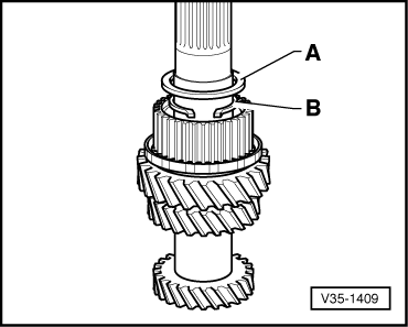
| 18 - | Circlip |
| q | Removing and installing → Fig. |
| q | Re-determining thickness → Fig. |
| 19 - | Shim for needle bearing for 1st speed selector gear |
| q | Removing and installing → Fig. |
| 20 - | Locking collar for 1st and 2nd gear |
| q | Installation position: splines for reverse gear towards synchro-ring for 2nd gear |
| 21 - | Synchro-ring for 1st gear |
| q | Checking for wear → Fig. |
| 22 - | Needle bearing for 1st speed selector gear |
| q | Lubricate with gear oil before installing |
| 23 - | 1st speed selector gear |
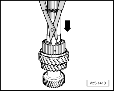
| q | Before installing, insert spring → Fig. |
| q | After pressing on → Item, check axial clearance (0.15 ... 0.35 mm) |
| 24 - | Inner race for small tapered roller bearing 1) |
| q | Pressing off → Fig. |
| q | Pressing on → Fig. |
| q | Low-friction bearing; do not oil bearing when measuring friction torque |
| 25 - | Outer race for small tapered roller bearing 1) |
| q | Driving out → Fig. |
| q | Pressing in → Fig. |
| 26 - | Shim “S4” |
| q | Table of adjustments → Anchor |
| 27 - | Intermediate housing 1) |
| q | Servicing → Chapter |
| 28 - | 6th gear wheel |
| q | Pressing off → Anchor |
| q | Pressing on → Anchor |
| q | Installation position: shoulder towards inner race for small tapered roller bearing |
| 29 - | Spacer sleeve |
| 30 - | Shim |
| q | Re-determining thickness → Anchor |
| 31 - | 5th gear wheel |
| q | Pulling off → Anchor |
| q | Driving on → Anchor |
| 32 - | Circlip for 5th gear wheel |
| q | Re-determining thickness → Anchor |
| 33 - | End cover |
| q | Servicing → Chapter |
Note
|
|
|
|
|
|
 WARNING
|
|
|
|
|
|
Note
|
|
|
|
|
|
| Available circlips - Thickness in mm 1) | ||||
| 2.34 | 2.40 | 2.46 | ||
| 2.36 | 2.42 | 2.48 | ||
| 2.38 | 2.44 | |||
| ||||
|
Note
|
|
|
|
|
|
Note
|
|
|
|
|
|
| Available circlips - Thickness in mm 1) | ||||
| 1.90 | 1.96 | 2.02 | ||
| 1.93 | 1.99 | |||
| ||||
|
|
|
|
|