audi Workshop Repair Guides

Audi Workshop Service and Repair Manuals

Checking compression > < Removing cylinder head (right-side)
Installing cylinder head
Procedure
  Note
t  Renew the cylinder head bolts.
t  Renew self-locking nuts and bolts when performing assembly work.
t  Renew bolts which are tightened to a specified angle as well as oil seals and gaskets.
t  If repairing, carefully remove any remaining gasket material from the cylinder head and cylinder block. Ensure that no long scores or scratches are made on the surfaces.
t  Carefully remove any remaining emery and abrasive material.
t  No oil or coolant must be allowed to remain in the blind holes for the cylinder head bolts in the cylinder block.
t  Do not remove new cylinder head gasket from packaging until it is ready to be fitted.
t  Handle gasket very carefully. Damage to the silicone coating or the indented area will lead to leaks.
t  Position cylinder head gasket on dowel sleeves. The word “oben” (top) or the Part No. should face towards the cylinder head.
t  Cylinder heads which have cracks between the valve seats or between a valve seat insert and the spark plug thread can be re-installed without reducing service life, provided the cracks are only slight and do not exceed a maximum of 0.3 mm in width, and no more than the first 4 turns of the spark plug threads are cracked.
t  When renewing a cylinder head, a sealing cap must be driven into the front of the cylinder head → Fig..
t  When installing an exchange cylinder head with the camshafts fitted, the contact surfaces between bucket tappet and cam running surface must be oiled after installation of the cylinder head.
t  The plastic protectors fitted to protect the open valves should not be removed until the cylinder head is ready to be fitted.
t  Secure all hose connections with the correct type of hose clips (same as original equipment) → Parts catalogue.
t  If engine oil is contaminated, perform oil change.
t  When fitting a new cylinder head or cylinder head gasket, drain off all the old coolant and refill with new coolant.
   
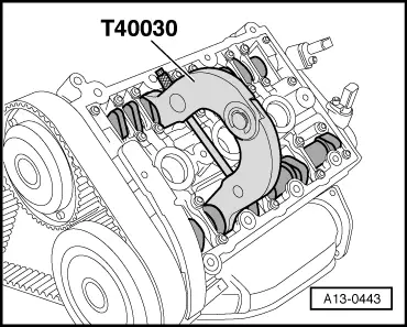
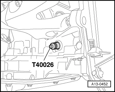
–  Before installing cylinder head, set crankshaft and camshafts to TDC:
l  The camshaft clamp -T40030- must be attached to both cylinder heads.
  A13-0443
l  The locking pin -T40026- must be screwed into the crankshaft.
  A13-0452
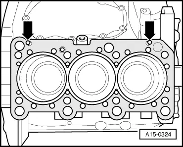
–  Fit cylinder head gasket.
l  Note position of centring pins -arrows- in cylinder block.
l  Check installation position of cylinder head gasket: the word “oben” (top) or the Part No. should face towards the cylinder head.
  A15-0324
–  Fit cylinder head.
–  Insert new cylinder head bolts and tighten hand-tight.
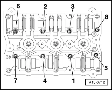
–  Tighten cylinder head bolts in 3 stages in the sequence indicated:
1.  Tighten with torque wrench to 40 Nm.
2.  Turn 90° (1/4 turn) further using a rigid wrench.
3.  Turn 90° (1/4 turn) further using a rigid wrench.
  Note
Cylinder head bolts do not have to be torqued down again later after repair work.
Remaining installation steps are carried out in reverse sequence; note the following:
–  Install toothed belt (adjust valve timing) → Anchor.
  Note
After working on the valve gear, turn the engine carefully at least 2 rotations by hand to ensure that none of the valves make contact when the starter is operated.
Rest-of-world vehicles:
–  Install front exhaust pipe (left-side) with starter catalytic converter and main catalytic converter: vehicles with manual gearbox or multitronic gearbox 01J → Chapter; vehicles with automatic gearbox 01V → Chapter.
–  Install front exhaust pipe (right-side) with starter catalytic converter and main catalytic converter: vehicles with manual gearbox or multitronic gearbox 01J → Chapter; vehicles with automatic gearbox 01V → Chapter.
–  Align exhaust system so it is free of stress: vehicles with front-wheel drive → Chapter, vehicles with four-wheel drive → Chapter.
USA models:
–  Install front exhaust pipe (left-side) with catalytic converter: vehicles with manual gearbox → Chapter, vehicles with multitronic gearbox 01J → Chapter; vehicles with automatic gearbox 01V → Chapter.
–  Remove front exhaust pipe (right-side) with catalytic converter: vehicles with manual gearbox → Chapter, vehicles with multitronic gearbox 01J → Chapter; vehicles with automatic gearbox 01V → Chapter.
–  Align exhaust system so it is free of stress: vehicles with front-wheel drive → Chapter, vehicles with four-wheel drive → Chapter.
All models:
–  Fit centring pin for intake manifold and install intake manifold → Chapter.
–  Observe notes on procedures required after connecting battery → Rep. Gr.27.
–  Fill cooling system with fresh coolant → Anchor.
–  Top up power steering fluid and bleed steering system → Rep. Gr.48.
Tightening torques
  A15-0712
ComponentNm
Coolant pipe (rear) to cylinder head10
Combination valve for secondary air system to cylinder head10
Toothed belt cover (rear) to cylinder head/ cylinder block10 1)
Bracket for idler roller to cylinder head10 1)
Front coolant pipe to cylinder headM610
M823
Power steering pressure pipe to:Power steering pump47
Cylinder head10
Coolant pipe (rear)20
Front cross member to body55
l  1) Renew bolts.


Checking compression > < Removing cylinder head (right-side)