
A4 Mk2
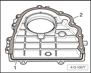
|
|
|
|
|
|
|
|
|
|
|
 WARNING
 Note
Note
|
|
|
|
|
|
| Stage | Tightening | ||
| I |
| ||
| II |
| ||
| III |
|
|
|
|
|
 Caution
|
|
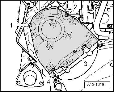
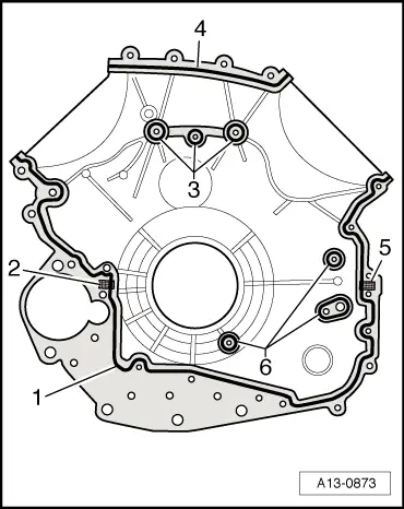
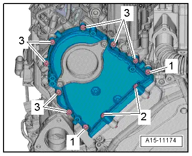
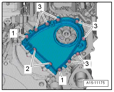
| Stage | Bolts | Tightening torque |
| 1. | -1- | 3 Nm |
| 2. | -2- | 9 Nm |
| 3. | -1- | 9 Nm |
| 4. | -3- | 9 Nm in diagonal sequence |
|
|
|
|
|
|
|
|
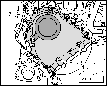
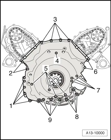
| Stage | Bolts | Tightening torque |
| 1. | -1- | 3 Nm |
| 2. | -2- | 9 Nm |
| 3. | -1- | 9 Nm |
| 4. | -3- | 9 Nm in diagonal sequence |
|
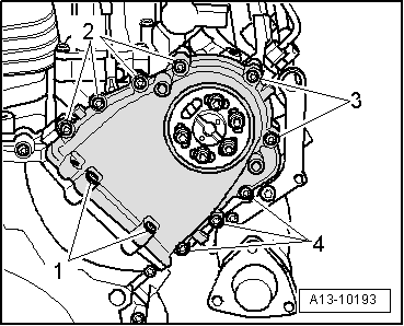
| Component | Nm | |
| Timing chain cover (bottom) to engine | M6 | 9 |
| M8 | 23 | |