audi Workshop Repair Guides

Audi Workshop Service and Repair Manuals

Renewing valve stem oil seals with cylinder head installed > < Removing and installing camshafts - cylinder head (left-side)
Removing and installing camshafts - cylinder head (right-side)
   
Removing and installing camshafts - cylinder head (right-side)
Special tools and workshop equipment required
t  Puller -T10320- for vehicles from 09.2005 onwards
t  Camshaft fitting tool -T40094-
t  Camshaft fitting tool -T40095-
t  Camshaft fitting tool -T40096-
t  Electric drill with plastic brush attachment
t  Safety goggles
t  Sealant → Electronic parts catalogue

Removing
–  Remove camshaft timing chain (right-side) from camshafts → Chapter.
–  Remove cylinder head cover (right-side) → Chapter.
   
–  Unscrew retaining frame bolts and nuts in the sequence -17 ... 1-.
  Note
Make sure you do not damage roller rocker fingers and compensation elements when removing camshafts.
–  Carefully remove retaining frame and camshafts.
Installing
  Caution
The camshafts MUST be installed using the camshaft fitting tool -T40094- as described in the following, as the thrust bearings in the retaining frame would otherwise be destroyed. The cylinder head would then have to be renewed.
  WARNING
Wear safety goggles.
–  Remove remaining sealant from cylinder head and retaining frame using rotating plastic brush or similar.
  Caution
Make sure that no sealant residue gets into the cylinder head or the bearings.
–  Clean sealing surfaces; they must be free of oil and grease.
–  Lubricate running surfaces of camshafts.
  A15-11171
Set up camshaft fitting tool -T40094- as follows:
–  Insert support -T40094/2- in position -B-.
–  Insert support -T40094/1- in position -C-.
  A15-10009
–  Place exhaust camshaft -1- in supports -T40094/1- and -T40094/2-.
–  Turn exhaust camshaft in such a way that it can be locked in „TDC“ position using locking device -arrow-.
  A15-11088
–  Place inlet camshaft -2- in camshaft fitting tool -T40094-.
l  The locating bar -3- must engage in the groove on the inlet camshaft.
–  Place camshaft fitting tool -T40096- on teeth of inlet camshaft in such a way that the two arms of the tool engage on the two halves of the gear (one in each half, as shown in illustration).
–  Tighten the clamping tool using the knurled wheel so that the faces of the gear teeth are in alignment.
–  Slide exhaust camshaft -1- towards inlet camshaft -arrows- until gear teeth engage.
  A15-11089
–  Check that camshafts are in correct position:
l  Recesses -arrows- on both camshafts must point outwards.
  A15-11169
–  Fit retaining frame -1- on both camshafts.
l  All camshaft bearings must be seated on the camshafts.
–  Attach camshaft fitting tool -T40095- to camshafts (align arms of bracket as required and tighten knurled nuts -2-).
–  Apply tension to camshafts by tightening the knurled nuts -3- upwards.
  A15-11091
–  Check if dowel pins -arrows- are fitted in cylinder head. Install missing dowel pins.
  Note
  A15-11173
Note the use-by date of the sealant.
–  Cut off nozzle of tube at front marking (nozzle Ø approx. 1.5 mm).
  Note
  A17-0081
For illustration purposes, the retaining frame is shown without the camshafts.
–  Turn retaining frame upside down.
  Caution
Make sure lubrication system is not clogged by excess sealant.
The sealant beads must not be thicker than specified.
–  Apply beads of sealant -arrows- onto clean sealing surfaces of retaining frame as shown in illustration.
l  The grooves on the sealing surface must be completely filled with sealant.
l  The beads of sealant must project 1.5 … 2.0 mm above the sealing surface.
  Note
The retaining frame must be installed within 5 minutes after applying the sealant.
  Caution
Risk of damage to engine.
Ensure that all roller rocker fingers contact the valve ends and compensation elements correctly.
  A15-11170
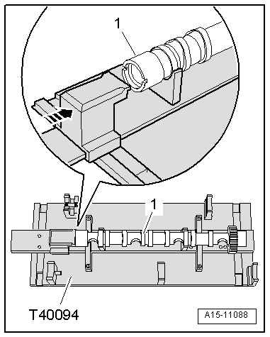
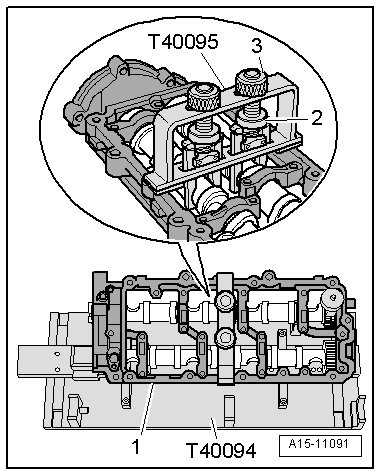
–  Fit retaining frame together with both camshafts and camshaft fitting tool -T40095- onto cylinder head.
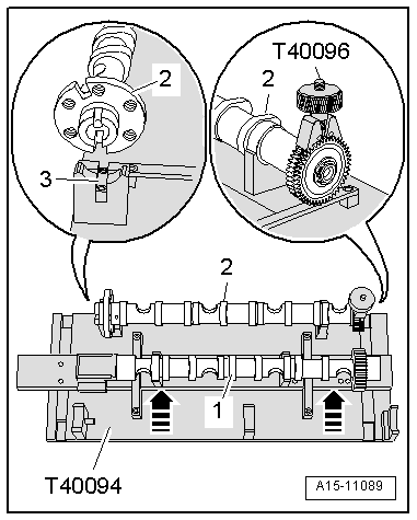
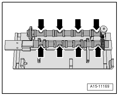
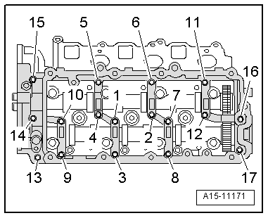
–  Tighten bolts for retaining frame → Fig..
–  Remove camshaft fitting tool -T40095- and -T40096-.
Remaining installation steps are carried out in reverse sequence; note the following:
  Note
t  After installing camshafts, wait for approx. 30 minutes before starting engine. Hydraulic valve compensation elements have to settle (otherwise valves will strike pistons).
t  After working on the valve gear, turn the engine carefully at least 2 rotations by hand to ensure that none of the valves make contact when the starter is operated.
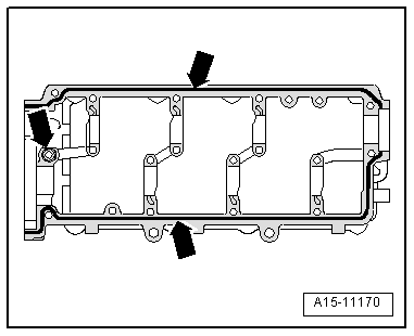
–  Install cylinder head cover (right-side) → Chapter.
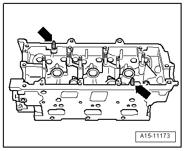
–  Renew sealing cap (front) on cylinder head.
–  Using a suitable drift, knock in new sealing cap (core plug) until flush.
–  Install camshaft timing chain → Anchor.
Tightening torque
  A15-11171
ComponentNm
Retaining frame to cylinder head9


Renewing valve stem oil seals with cylinder head installed > < Removing and installing camshafts - cylinder head (left-side)