audi Workshop Repair Guides

Audi Workshop Service and Repair Manuals

Removing and installing engine - vehicles with automatic gearbox > < Securing engine to engine and gearbox stand
Installing engine
Installing engine
  Note
t  Renew self-locking nuts and bolts when performing assembly work.
t  Renew bolts which are tightened to a specified angle as well as oil seals, gaskets and O-rings.
t  Secure all hose connections with the correct type of hose clips (same as original equipment) → Parts catalogue.
t  Fit all heat insulation sleeves in the original position when installing.
t  Fit all cable ties in the original positions when installing.
–  When fitting a new clutch plate together with a used pressure plate (self-adjusting clutch), the adjuster ring in the pressure plate has to be reset by turning it back as far as it will go. If this is not done, the pressure plate will operate with reduced clamping force, causing clutch slip → Rep. Gr.30.
  Note
t  If the clutch plate is not being replaced, it is not necessary to reset the adjuster ring.
t  New SAC pressure plates are already pre-set accordingly, and do not have to be reset.
–  Clean input shaft splines and (in the case of used clutch plates) the hub splines. Remove corrosion and apply only a very thin coating of grease ( → Parts catalogue) to the splines. Do not lubricate guide sleeve.
–  Check that the clutch plate is properly centralised (only necessary if you have carried out other work on the clutch).
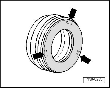
–  Check clutch release bearing for wear; renew if necessary.
If the plastic ring for release bearing is loose:
   
–  Bond plastic ring for release bearing to bearing race using adhesive → Parts catalogue.
l  Three square lugs -arrows- on the plastic ring engage in the recesses in the bearing race.
l  The release bearing must be renewed if it has scoring deeper than 0.5 mm.
–  Check whether dowel sleeves for centring the engine/gearbox assembly are fitted in the cylinder block; install dowel sleeves if necessary.
–  Press intermediate plate between engine and gearbox onto dowel sleeves.
–  Bolt gearbox to engine.
  Note
t  Tightening torques apply only to lightly greased, oiled, phosphated or black-finished nuts and bolts.
t  Additional lubricant such as engine oil or gearbox oil may be used, but do not use lubricant containing graphite.
t  Do not use degreased parts.
t  Tolerance for tightening torques ± 15%.
  N30-0285
Securing engine to gearbox
  A10-1641
ItemBoltNm
1, 2M12×12065
3M12×11065
4, 5M12×10565
6M12×13065
7M12×17065
8, 9, 10M10x6045
ADowel sleeves for centralising

Remaining installation steps are carried out in reverse sequence; note the following:
–  Install front exhaust pipes together with catalytic converters: left-side → Chapter, right-side → Chapter.
–  The threaded holes in the flange shaft for the propshaft on the gearbox must be cleaned of remaining locking fluid with a thread tap before assembling.
   
–  Screw down the spindles for support elements (left-side) at engine/gearbox assembly.
–  Unscrew both base plates for support elements (left-side) at scissor-type assembly platform -VAS 6131 A-.
  A10-10225
–  Screw down the spindles for support elements (right-side) at engine/gearbox assembly.
–  Unscrew both base plates for support elements (right-side) at scissor-type assembly platform -VAS 6131 A-.
  Note
The mounting points for engine (front) and tunnel cross member remain unchanged.
  A10-10226
–  Set up scissor-type assembly platform -VAS 6131 A- with support set for Audi -VAS 6131/10- as follows:
  A10-1764
Platform coordinatesParts of support set for Audi -VAS 6131/10-
B4 → Note/10-1/10-4/10-5/10-11
G3 → Note/10-1/10-4/10-5/10-11
B10/10-1/10-2/10-5/10-8 → Note
G10/10-1/10-2/10-5/10-8 → Note
C14 → Note/10-1/10-3/10-5/10-7
E14 → Note/10-1/10-3/10-5/10-7

1)  Support elements remain unchanged.
2)  Secure support elements only after installing the subframe.
   
–  Fit subframe onto the two support elements -VAS 6131/10-8-.
–  Screw up the spindles for support elements on both sides.
–  Tighten base plates for support elements to 20 Nm on scissor-type assembly platform -VAS 6131 A-.
–  Slowly guide engine gearbox assembly together with subframe into the body from below using scissor-type assembly platform -VAS 6131 A-.
  A10-10133
–  Raise the engine/gearbox assembly using scissor-type assembly platform -VAS 6131 A- until the distance -a- is reached.
l  Dimension -a- = 100 mm.
  A10-10106
–  Secure clutch slave cylinder with new bolt -arrow-.
  A34-0641
–  Install selector shaft lever -arrow-.
  A34-10014
–  Secure connecting rod -2- of selector rod.
–  Screw in hexagon socket head bolt for push rod -1-.
  N34-1208
–  Adjust the subframe, consoles for engine mountings and tunnel cross member according to the markings made on the longitudinal members during removal.
–  Only tighten bolts for subframe, consoles for engine mountings and tunnel cross member to the specified torque (do not turn further); tighten bolts to final torque only after performing wheel alignment check.
1 - 65 Nm
2 - 110 Nm
3 - 110 Nm
4 - 75 Nm
  WARNING
The vehicle must not be driven at this stage.
–  Install drive shafts → Rep. Gr.40.
–  Install guide links, track control links, anti-roll bar and suspension struts → Rep. Gr.40.
–  Install propshaft → Rear final drive 01R and 0AR; Rep. Gr.39.
–  Align exhaust system so it is free of stress → Chapter.
–  Install refrigerant lines → Rep. Gr.87.
  A10-10224
USA vehicles:
–  Secure fuel hose at connection for fuel rail pipe. To do so, counterhold at hexagon flats -1- and -3- with open-end spanners and tighten union nut -2-: tightening torque 22 Nm.
  A20-1202
All models:
–  Install lock carrier with attachments → Rep. Gr.50.
–  Allow stop for torque reaction support to rest on rubber buffer for torque reaction support under its own weight and tighten bolts -arrows-.
–  Install bumper cover (front) → Rep. Gr.63.
–  Electrical connections and routing → Current flow diagrams, Electrical fault finding and Fitting locations.
–  Observe notes on procedures required after connecting battery → Rep. Gr.27.
  Caution
Do not use a battery charger to boost starting. There is danger of damaging the vehicle's control units.
–  Install and adjust wiper arms → Rep. Gr.92.
–  Check oil level → Chapter.
–  Before starting engine, top-up hydraulic fluid in power steering reservoir → Rep. Gr.48.
  Note
The power steering pump must not be run when dry.
–  Fill cooling system → Anchor.
  Note
t  Drained-off coolant may only be used again if the original cylinder head and cylinder block are re-installed.
t  Contaminated or dirty coolant must not be used again.
–  Charge the refrigerant system → Air conditioner system - with refrigerant R134a.
–  Adjust subframe and the two consoles for engine mountings → Rep. Gr.40.
–  Perform wheel alignment check → Rep. Gr.44.
  WARNING
Tighten bolts for subframe to final setting after performing wheel alignment check.
–  Check headlight adjustment → Booklet803 or → Booklet805.
Tightening torques
  Note
t  Tightening torques apply only to lightly greased, oiled, phosphated or black-finished nuts and bolts.
t  Additional lubricant such as engine oil or gearbox oil may be used, but do not use lubricant containing graphite.
t  Do not use degreased parts.
t  Tolerance for tightening torques ± 15 %.
  A13-0633
ComponentNm
Bolts/nutsM69
 M820
 M1040
 M1265
Except for the following: 
Engine support to engine42 → Note
Clutch slave cylinder to gearbox23 → Note
Selector shaft lever to gearbox23
Push rod to gearbox40
Connecting rod for selector rod to gearbox23
Drive shaft heat shield to gearbox23
Hydraulic pressure pipe40
Stop for torque reaction support to lock carrier28
Fuel hose to fuel line22

3)  Install using locking fluid; locking fluid → Parts catalogue.
4)  Renew bolt.
   

Removing and installing engine - vehicles with automatic gearbox > < Securing engine to engine and gearbox stand