audi Workshop Repair Guides

Audi Workshop Service and Repair Manuals

Checking initial fuel pressure up to mechanical high-pressure pump > < Installation position of high-pressure injectors, air guides, high-pressure pump, coolant pipe
Motronic Direct Injection and Ignition System (4-Cyl.)
Servicing injection system
Removing and installing injectors, replacing combustion-chamber sealing ring (Teflon sealing ring)

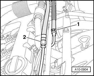
Always follow pressure dissipation procedure, Page 24-4.

Note:

Use the exploded views on the previous pages.

The combustion-chamber sealing ring (Teflon) and the O-ring must always be replaced.

The injectors can only be accessed after removal of the intake manifold and fuel rail with load motion flap for air flow control. (Additional or fewer steps may be required depending on the version.)

Observe the illustrations on the previous pages as they also give the tightening torques.

 
A10-0904
  • ‒ → Disconnect fuel supply line -2- (25 Nm) and fuel return line -1- (collect discharged fuel).
  • ‒ Disconnect the two hoses from cylinder-head cover.
  • ‒ Undo the four hose clamps on intake manifold.
  • ‒ Detach coolant expansion tank and put to one side.
  • ‒ Disconnect hoses from throttle valve.
  • ‒ Pull out dipstick.
  • ‒ Unscrew nuts securing intake manifold (2x).
  • ‒ Lift back intake manifold.
  • ‒ Disconnect coolant hose from throttle valve (collect any discharged water).
  • ‒ Remove bolt for dipstick holder and then pull out dipstick holder.
  • ‒ Disconnect fuel lines from high-pressure pump (lines have "ridge" at the bolt-on point to ensure tightness and correct attachment of line). Pay attention to this when reinstalling lines. Observe tightening torques .
  • ‒ Unplug connector at intake manifold flap motor -V157.
  • ‒ Remove oil separator for crankcase breather.
  • ‒ Unscrew bolts securing fuel rail (see illustrations on previous pages).
  • ‒ Detach fuel rail with load motion flap from injectors.
  • ‒ Unplug connectors from injectors.

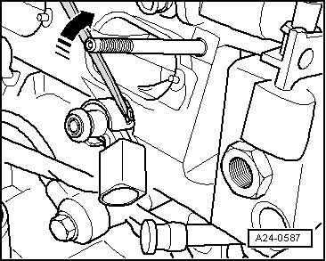
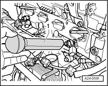
Removing injectors

Injectors may remain lodged in cylinder head. Special tools have been designed for this eventuality. Their use is described below.

Note:

  • ◆ You will need the tool box containing the special tool T10133 to remove the injectors and to replace the combustion-chamber sealing ring (Teflon sealing ring).
 
A24-0533
  • ‒ → Illustration shows injector when removed. How to remove injector is described on following pages.
  •     1 -    Radial compensation element, replace if damaged
  •     2 -    Combustion-chamber sealing ring (Teflon sealing ring), replace; when fitting, do not grease ring or treat it with any other lubricant
  •     3 -    Chamfer on injector
 
A24-0533
  • ‒ → Illustration shows injector when removed.
  •     4 -    Spacer ring (replace if damaged)
  •     5 -    O-ring (replace; apply thin coating of clean engine oil prior to installation)
  •     6 -    Support ring (via this support ring, fuel rail exerts force which secures injector in cylinder head)

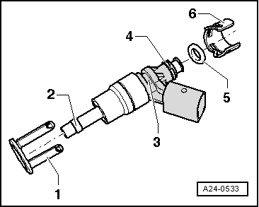
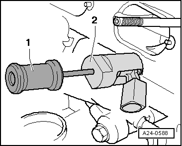
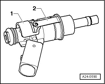
Note:

When the injector is fitted, the radial compensation element (Item 1 in illustration above, previous page) is clipped into the support ring (Item 6). To remove the injector, the support ring must be removed from the injector so that the extractor T10133/2 can be inserted into the chamfer on the injector (Item 3, previous illustration).

 
A24-0587
  • ‒ → Use a screwdriver to bend retainer tabs of radial compensation element to side, and pull support ring off injector.
 
A24-0588
  • ‒ → Screw striker T10133/3 (Item 1) onto extractor T10133/2 (Item 2). Then insert extractor T10133/2 into chamfer on injector and carefully knock out injector. This may result in destruction of radial compensation element (retainer tabs break off). It must be replaced when injector is refitted.

Replacing combustion-chamber sealing ring (Teflon sealing ring)

 
A24-0533
  • ‒ → Illustration shows injector when removed.
  •     1 -    Radial compensation element (replace if damaged)
  •     2 -    Combustion-chamber sealing ring (Teflon sealing ring), replace; when fitting, do not grease ring or treat it with any other lubricant
  •     3 -    Chamfer on injector
  •     4 -    Spacer ring (replace if damaged)
  •     5 -    O-ring (replace; apply thin coating of clean engine oil prior to installation)
  •     6 -    Support ring (via this support ring, fuel rail exerts force which secures injector in cylinder head)

The combustion-chamber sealing ring must always be replaced prior to reinstalling the high-pressure injector.

  • ‒ Carefully remove old Teflon ring using suitable tools (e.g. cut open ring using razor blade, splay open ring with small screwdriver and then pull forwards to remove). It is essential to ensure that groove and continuous ridge in groove land are not damaged.

Note:

The injector must be replaced if the groove is damaged.

  • ‒ Before new Teflon ring is fitted, any combustion residue must be removed from sealing ring groove and injector shaft using a clean cloth.

Note:

 
A24-0571

The illustration shows an injector with "offset connector". This can be ignored since it is not relevant when replacing the combustion-chamber sealing ring.

  • ‒ Use assembly cone T10133/5 and assembly sleeve T10133/6 to fit new Teflon ring.
  • ‒ → Slide Teflon ring onto assembly cone. Then use assembly sleeve to push Teflon ring smoothly off assembly cone into injector groove. Do not use any lubricants.

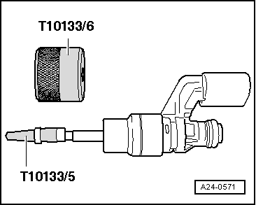
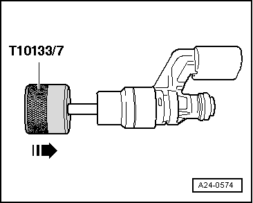
Note:

The Teflon ring is widened when it is pushed onto the injector. The Teflon ring must therefore be narrowed again after it has been fitted. This is done in two steps. The procedure is described below.

Step 1 of Teflon ring calibration (adaption) involves special tool T 10133/7.

 
A24-0574
  • ‒ → Rotate special tool (approx. 180°) while simultaneously sliding it over injector as far as it will go, applying moderate force. Then pull back to original position, once again rotating by 180°.

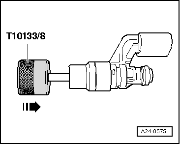
Step 2 of Teflon ring calibration (adaption) involves special tool T 10133/8.

 
A24-0575
  • ‒ → Rotate special tool (approx. 180°) while simultaneously sliding it over injector as far as it will go, applying moderate force. Then pull back to original position, once again rotating by 180°.
 
A24-0589
  • ‒ → Use supplied nylon brush (special tool T10133/4) to thoroughly clean holes in high-pressure injectors in cylinder head prior to installing injector.

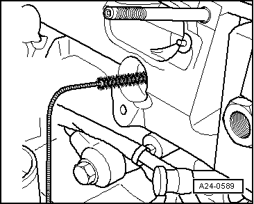
Note:

An open inlet valve may prevent cleaning. If so, the engine must be cranked by hand by rotating the crankshaft with a spanner.

 
A24-0590
  • ‒ → Refit support ring -Item 1- on injector and clip radial compensation element -Item 2- onto support ring.
 
A24-0591
  • ‒ → Use assembly drift T10133/9 to push injector as far as it will go into hole provided in cylinder head. Make sure that injectors are correctly positioned in cylinder head =>see illustration on Page 24-31.

Install in reverse order

Important: The following points must always be observed:

  • ● Coat O-rings of high-pressure injectors with clean engine oil to facilitate insertion into fuel rail.
  • ● Replace all gaskets.
  • ● Fuel rail must be positioned on injectors and pressed in evenly.
  • ● It is essential to observe torque specifications .

Checking initial fuel pressure up to mechanical high-pressure pump > < Installation position of high-pressure injectors, air guides, high-pressure pump, coolant pipe