
A4 Mk2
 |
|
|
 |
|
|
 |
|
|
 |
|
|
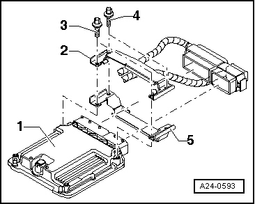
→ To render access to connectors at engine control unit more difficult, engine control unit -1- is bolted to a sheet-metal housing -5- by way of a catch -2- and shear bolts -3- and -4-. |
 |
|
|
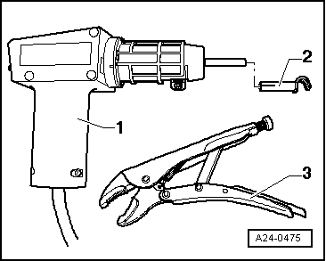
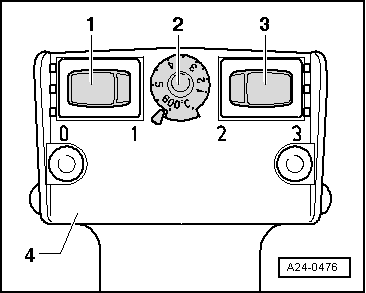
Tools required:
Attention:
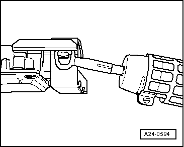
Heating the thread of the catch also greatly increases the temperature of the shear bolts and sheet-metal housing components. Take care to avoid burns. It is also important to ensure that only the thread is heated and none of the surrounding components if at all possible (these should be covered if necessary). |
|
|
|
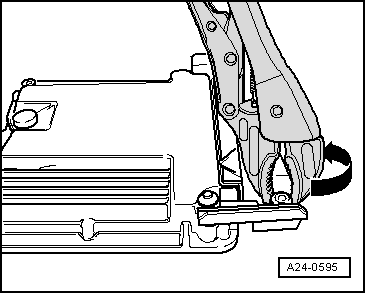
→ The threads of the two shear bolts -Item 4- (which are not bolted to the engine control unit) are coated with a locking fluid. The threads must therefore be heated using the hot-air blower to allow the two bolts to be screwed out. → The threads of the two shear bolts which are bolted to the engine control unit -Item 3- are not coated with a locking fluid. The thread in the control unit housing should not and need not be heated (unpermissible heating of the engine control unit). |
 |
|
|
 |
|
Attention:
Heating the thread of the catch also greatly increases the temperature of the shear bolts and sheet-metal housing components. Take care to avoid burns. It is also important to ensure that only the thread is heated and none of the surrounding components if at all possible (these should be covered if necessary). |
 |
|
|
 |
|
Installing Install in reverse order, paying attention to the following: The following steps must be performed after connecting new engine control unit:
Vehicle diagnostic, testing and information system VAS 5051 must be used for this purpose.
|