
A4 Mk2
|
|
|
|
|
 WARNING
|
|
|
|
|
|
|
|
|
|
|
|
|
|
|
|
|
|
|
|
|
|
|
|
|
|
|
|
|
|
|
|
|
|
 Note
Note |
|
|
|
|
|
Note
|
|
Note
Note |
|
|
|
|
|
Note
|
|
|
|
Note
Note
|
|
|
|
| Component | Nm |
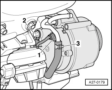
| Coolant pipes to alternator | 9 |
| Terminal 30/B+ to alternator | 16 |
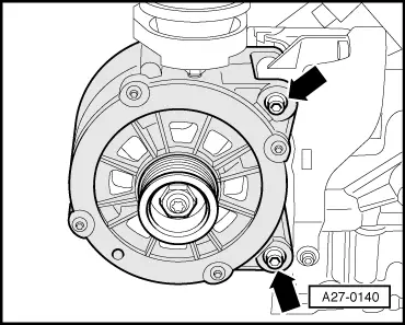
| Alternator to engine | 22 |
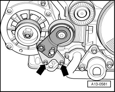
| Tensioning roller to engine | 22 |