audi Workshop Repair Guides

Audi Workshop Service and Repair Manuals

Removing and installing air quality sensorG238 / humidity sender in fresh air intake ductG657 > < Test requirements
Checking operation of G238
Checking operation of -G238-
Vehicles with a high-voltage system (hybrid vehicles)
For all work on vehicles with a high-voltage system, pay attention to the additional warnings for such vehicles → Chapter and → Electrical system; Rep. gr.93.
As work in the vicinity of high-voltage system components is necessary for the following sequence of operations, perform „Visual inspection of high-voltage components and cables for damage“ → Chapter and heed the „General warnings for working on high-voltage system“ → Electrical system; Rep. gr.93
  WARNING
Danger from unexpected engine starting
When performing general work on vehicles with a high-voltage system, switch off the ignition and remove the ignition key from the passenger compartment.
  WARNING
Working on vehicles with high-voltage wiring:
l  Do not support yourself or tools on high-voltage wiring or associated components --> this can damage the insulation.
l  High-voltage wiring must not be excessively bent or kinked --> this can damage the insulation.
l  The round high-voltage connectors are colour-coded with an external coloured ring and are provided with mechanical coding or guide lugs. It is important to observe this coding when joining up the round high-voltage connectors, otherwise the connectors can be damaged.
  DANGER!
Risk of fatal injury if high-voltage components are damaged.
Observe the following when working in the vicinity of high-voltage components or wiring:
t  It is not permitted to use cutting or forming tools, other sharp-edged tools or heat sources such as welding, brazing, soldering, hot air or thermal bonding equipment.
t  Before starting work, visually inspect the high-voltage components in the areas involved.
t  Before working in the engine compartment, visually inspect the power electronics -JX1-, electric drive motor -V141-, air conditioner compressor -V470- and high-voltage wiring.
t  Before working on the vehicle underbody, visually inspect the high-voltage wiring and covers.
t  Before working on the rear section of the vehicle, visually inspect the high-voltage wiring and the electro-box with the maintenance connector for high-voltage system - TW -.
t  Visually inspect all potential equalisation lines.
Check the following when making the visual inspection:
t  There must be no external damage on any component.
t  The insulation of the high-voltage wiring and potential equalisation lines must not be damaged.
t  There must be no unusual deformation of the high-voltage wiring.
t  All high-voltage components must be identified by a red warning sticker.
–  Switch off the ignition.
   
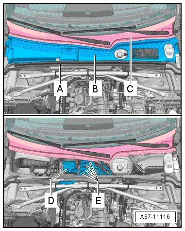
–  Remove the rubber seal -A- and the plenum chamber cover -B- (different versions) → General body repairs, exterior; Rep. gr.50.
t  After removing the plenum chamber cover -B-, visually inspect the high-voltage components -D- (in this case the power and control electronics for electric drive -JX1-) and the high-voltage cables -E- → Chapter and → Electrical system; Rep. gr.93
t  When working in the area of high-voltage components -D- and high-voltage cables -E- always make sure that these components are not damaged → Electrical system; Rep. gr.93.
t  On completion of work and before fitting the plenum chamber cover -B-, visually inspect the high-voltage components -D- and the high-voltage cables -E- → Electrical system; Rep. gr.93.
Working with ignition switched on or high-voltage system active
  DANGER!
Danger from unexpected engine starting and risk of poisoning in enclosed areas when working with the ignition switched on or with READY activated. Risk of parts of the body and/or clothing becoming trapped or caught up.
Take the following action before switching on the ignition:
t  Move the selector lever to position P
t  Activate the parking brake
t  Switch off the ignition
t  Open the bonnet
t  Connect a charger, e.g. Battery charger -VAS 5095A- to the jump start points of the 12 V vehicle electrical system
t  Switch on the ignition
–  To minimise the number of automatic engine starts with READY active during checking and measurement work, the vehicle batteries must be charged e.g. with the Battery charger, 60A -VAS 5904- in battery back-up mode → Electrical system; Rep. gr.27 and → Electrical system; Rep. gr.93
–  For checking and measurement work where READY has to be active or the ignition switched on, set the selector lever to position „P“, activate the parking brake, arrange the necessary tools such that they cannot come into contact with rotating engine components and be sure to keep well away from rotating components when the engine is running.
  Note
t  The selector lever is also to be set to position „P“ and the parking brake activated for checking and measurement work where the ignition has to be switched on but READY does not have to be active.
t  READY is displayed in the control unit in dash panel insert -J285- via the „Powermeter“ → Owner's manual.
t  For READY activation and deactivation, refer to → Owner's manual (heed the display in the control unit in dash panel insert -J285- when doing so).
Vehicles with no high-voltage system
–  Switch off the ignition.
  A87-11116
–  Detach the rubber seal -B- on the left to the necessary extent → General body repairs, exterior; Rep. gr.50.
–  Remove the cover for the fresh air intake at the scuttle panel trim -A- or the scuttle panel trim (different versions) → General body repairs, exterior; Rep. gr.50.
  Note
If necessary, carefully detach the scuttle panel trim from the fastener at the cross-member of the windscreen -C- → General body repairs, exterior; Rep. gr.50.
All vehicles
–  With the ignition switched off, connect up the vehicle diagnostic, testing and information system -VAS 5051/- with the diagnostic cable -VAS 5051/5A- to the diagnostic connection in the vehicle and start guided fault-finding → "Guided fault-finding" function of vehicle diagnostic, testing and information system VAS 5051.
–  Switch on the ignition (vehicles with high-voltage system).
–  Start the engine (vehicles with no high-voltage system).
  Note
On vehicles with a start-stop system, the engine may be shut off automatically by the vehicle electronics.
–  Interrogate the event recorder of the operating and display unit, Climatronic control unit -J255- → "Guided fault-finding" function of vehicle diagnostic, testing and information system VAS 5051.
–  Set the operating and display unit, Climatronic control unit -J255- („Deluxe“ version) to „Auto“ mode.
–  Use the MMI (Multi Media Interface) on the operating and display unit, Climatronic control unit -J255- to set „Automatic air recirculation mode“ → Infotainment/MMI operating instructions.
–  Wait 2 minutes (warm-up time of air quality sensor -G238-).
–  Use the vehicle diagnostic, testing and information system -VAS 5051- to select the „Reading measured value block“ function and read out the measured values of the air quality sensor -G238- → "Guided fault-finding" function of vehicle diagnostic, testing and information system VAS 5051.
  Note
The measured value block displays the air pollution measured by the air quality sensor -G238- and the measured values for the NOx (nitrogen oxide) and CO (carbon monoxide) content of the air. For explanatory notes on the possible displays, refer to → "Guided fault-finding" function of vehicle diagnostic, testing and information system VAS 5051.
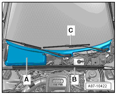
  A87-10422
–  Give the air quality sensor -G238--A- an approx. 90° anti-clockwise turn and remove it from the fresh air intake -C-.
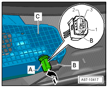
  A87-10417
–  Allow a small quantity of gas from a cigarette lighter -B- to flow from above past area -A- of the air quality sensor -G238-.
  Note
The air quality sensor -G238- reacts when exposed to cigarette smoke or cigarette lighter gas. As cigarette lighter gas is heavier than air, the air quality sensor -G238- is to be removed and the gas applied from above.
–  Select and read out the measured value block with the measured values of the air quality sensor -G238- → "Guided fault-finding" function of vehicle diagnostic, testing and information system VAS 5051.
Specifications:
t  The measured values in the display zones increase as compared to the initial value, thus indicating that both sensors in the air quality sensor -G238- are functioning properly and that the electronics in -G238- are evaluating the measured values correctly.
–  Wait briefly (approx.1 minute, depending on the amount of gas being applied to the sensor).
–  Read out the display in the display zones with the measured values of the air quality sensor -G238-.
Specifications:
t  The measured values in the display zones return to the initial levels, thus indicating that both sensors are functioning properly and the sensor electronics are evaluating the measured values correctly.
  Note
The values now displayed may differ from the first measurement due to changes in pollutant levels.
–  Read out the display with the measured values for the air conditioner operating status (air recirculation/fresh-air mode).
Specifications:
t  The display zone shows that the air conditioner is operating in fresh-air mode.
  Note
t  If the measured value block indicates a value other than „fresh-air mode“, air recirculation mode has already been requested (e.g. on account of „maximum cooling output“ request or „manual air recirculation mode“ setting). Select a mode in which air recirculation is not requested.
t  If the measured value block indicates that the air quality sensor -G238- is already requesting automatic air recirculation mode, clean the plenum chamber if necessary or move the vehicle to an area with a cleaner ambient atmosphere → "Guided fault-finding" function of vehicle diagnostic, testing and information system VAS 5051.
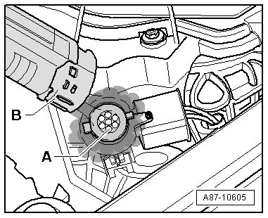
  A87-10605
–  Allow a small quantity of gas from a cigarette lighter -B- to flow from above past area -A- of the air quality sensor -G238-.
–  Read out the display for air recirculation/fresh-air mode.
Specifications:
t  The measured value block shows that air recirculation mode has been requested and the air conditioner is operating in air recirculation mode.
  Note
t  If the measured value block indicates that the air quality sensor -G238- is requesting automatic air recirculation mode, but that this request is not being implemented by the operating and display unit, Climatronic control unit -J255- on account of a shut-off criterion, eliminate the cause of this shut-off criterion if applicable → "Guided fault-finding" function of vehicle diagnostic, testing and information system VAS 5051.
t  To stop the air flow/fresh-air and air recirculation flaps being switched too frequently, an air quality sensor -G238- request for „Automatic air recirculation mode“ is applied for at least 25 seconds (minimum dwell time) even if the pollutant concentration in the air has decreased to such an extent that air recirculation mode would no longer be necessary.
–  Wait briefly (approx.1 minute, depending on the amount of gas being applied to the sensor).
t  The measured value block shows that air recirculation mode is no longer being requested and the air conditioner is operating in fresh-air mode again.
Proceed as follows if the air quality sensor -G238- functions properly in this test but a customer complaint has been received:
–  Check for contamination of the dust and pollen filter → Chapter.
–  With the ignition switched off, connect up the vehicle diagnostic, testing and information system -VAS 5051/- with the diagnostic cable -VAS 5051/5A- to the diagnostic connection in the vehicle and start guided fault-finding → "Guided fault-finding" function of vehicle diagnostic, testing and information system VAS 5051.
–  Use the vehicle diagnostic, testing and information system -VAS 5051- to select the „Reading measured value block“ function → "Guided fault-finding" function of vehicle diagnostic, testing and information system VAS 5051.
  Note
A second person is required, as the display values have to be read out whilst driving.
Heed the safety instructions → "Guided fault-finding" function of vehicle diagnostic, testing and information system VAS 5051
–  Alternately read out the displays in the measured value block for the measured values of the air quality sensor -G238- and the request for air recirculation/fresh-air mode.
–  Start by driving the vehicle into an area with a relatively clean atmosphere (system in fresh-air mode).
–  Then drive into a polluted area (e.g. an uphill road with lorry traffic).
–  Read out the displays in the various zones. The displays in the various zones must change, for example when driving through a cloud of diesel emissions.
  Note
Also pay attention to the descriptions → Chapter (removing and installing dust and pollen filter) and → Chapter „Mode of operation of air quality sensor -G238- and humidity sender in fresh air intake duct -G657-“.
  A87-10605

Removing and installing air quality sensorG238 / humidity sender in fresh air intake ductG657 > < Test requirements