audi Workshop Repair Guides

Audi Workshop Service and Repair Manuals

Checking, removing and installing passenger compartment forced air extractor > < Checking operation of G238
Removing and installing air quality sensorG238 / humidity sender in fresh air intake ductG657
Removing and installing air quality sensor -G238- / humidity sender in fresh air intake duct -G657-
  Note
t  Different versions are fitted depending on the vehicle production period and the type of air conditioner („Basic“ or „Deluxe“) → Chapter.
t  -G238- is only fitted on vehicles with air conditioner of the „Deluxe“ type.
t  -G657- is only being gradually introduced on vehicles as of Model Year 2012. → Chapter
   
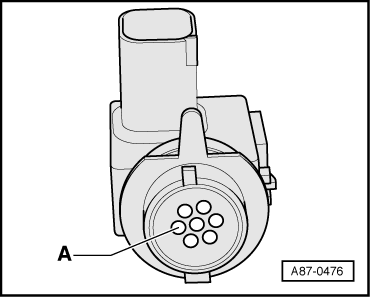
t  -G238- / -G657- is a highly sensitive electronic component which could be destroyed by direct exposure to solvents, fuels and certain chemical compounds (contamination can ingress by way of area -A- for example). For this reason, never fit a -G238- / -G657- which has been kept in a tool chest or the like.
t  Following removal, do not set down -G238- / -G657- in areas where it could come into contact with solvents, fuels or certain chemical compounds (liquids or vapours).
t  There are different versions of -G238- / -G657- with different modes of operation. Attention is therefore to be paid to the correct version → Electronic parts catalogue.
Vehicles with a high-voltage system (hybrid vehicles)
For all work on vehicles with a high-voltage system, pay attention to the additional warnings for such vehicles → Chapter and → Electrical system; Rep. gr.93.
As work in the vicinity of high-voltage system components is necessary for the following sequence of operations, perform „Visual inspection of high-voltage components and cables for damage“ → Chapter and heed the „General warnings for working on high-voltage system“ → Electrical system; Rep. gr.93
  WARNING
Danger from unexpected engine starting
When performing general work on vehicles with a high-voltage system, switch off the ignition and remove the ignition key from the passenger compartment.
  WARNING
Working on vehicles with high-voltage wiring:
l  Do not support yourself or tools on high-voltage wiring or associated components --> this can damage the insulation.
l  High-voltage wiring must not be excessively bent or kinked --> this can damage the insulation.
l  The round high-voltage connectors are colour-coded with an external coloured ring and are provided with mechanical coding or guide lugs. It is important to observe this coding when joining up the round high-voltage connectors, otherwise the connectors can be damaged.
  DANGER!
Risk of fatal injury if high-voltage components are damaged.
Observe the following when working in the vicinity of high-voltage components or wiring:
t  It is not permitted to use cutting or forming tools, other sharp-edged tools or heat sources such as welding, brazing, soldering, hot air or thermal bonding equipment.
t  Before starting work, visually inspect the high-voltage components in the areas involved.
t  Before working in the engine compartment, visually inspect the power electronics -JX1-, electric drive motor -V141-, air conditioner compressor -V470- and high-voltage wiring.
t  Before working on the vehicle underbody, visually inspect the high-voltage wiring and covers.
t  Before working on the rear section of the vehicle, visually inspect the high-voltage wiring and the electro-box with the maintenance connector for high-voltage system - TW -.
t  Visually inspect all potential equalisation lines.
Check the following when making the visual inspection:
t  There must be no external damage on any component.
t  The insulation of the high-voltage wiring and potential equalisation lines must not be damaged.
t  There must be no unusual deformation of the high-voltage wiring.
t  All high-voltage components must be identified by a red warning sticker.
–  Switch off the ignition.
  A87-0476
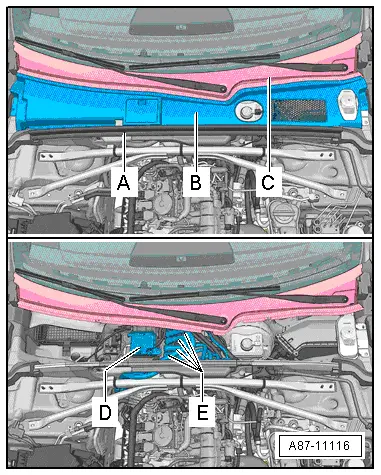
–  Remove the rubber seal -A- and the plenum chamber cover -B- (different versions) → General body repairs, exterior; Rep. gr.50.
t  After removing the plenum chamber cover -B-, visually inspect the high-voltage components -D- (in this case the power and control electronics for electric drive -JX1-) and the high-voltage cables -E- → Chapter and → Electrical system; Rep. gr.93
t  When working in the area of high-voltage components -D- and high-voltage cables -E- always make sure that these components are not damaged → Electrical system; Rep. gr.93.
t  On completion of work and before fitting the plenum chamber cover -B-, visually inspect the high-voltage components -D- and the high-voltage cables -E- → Electrical system; Rep. gr.93.
Vehicles with no high-voltage system
–  Switch off the ignition
  A87-11116
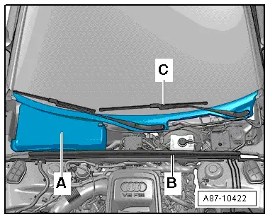
–  Detach the rubber seal -B- on the left to the necessary extent → General body repairs, exterior; Rep. gr.50.
–  Remove the cover for the fresh air intake at the scuttle panel trim -A- or the scuttle panel trim (different versions) → General body repairs, exterior; Rep. gr.50.
  Note
If necessary, carefully detach the scuttle panel trim from the fastener at the cross-member of the windscreen -C- → General body repairs, exterior; Rep. gr.50.
All vehicles
  A87-10422
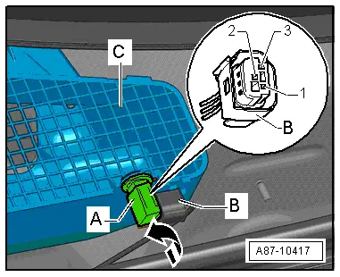
–  Give -G238- / -G657--A- an approx. 90° anti-clockwise turn and remove from the fresh air intake -C-.
–  Unplug the connector -B- from -G238- / -G657-.
Contact assignment in connector -B-
1 - Positive (terminal „15“)
2 - Negative (terminal „31“)
3 - Signal wire to onboard supply control unit -J519- → Current flow diagrams, Electrical fault finding and Fitting locations.
  Note
t  The signal emitted by -G238- / -G657- cannot be evaluated using workshop equipment.
t  The data of -G238- / -G657- is evaluated by the onboard supply control unit -J519- and transmitted to the operating and display unit, Climatronic control unit -J255- via the data bus.
t  There are different versions of the fresh air intake housing -C- (with and without mount for -G238- / -G657--A-, mount at front or on side). Pay attention to the correct version → Electronic parts catalogue.
t  The measured values of -G238- / -G657- are displayed in the measured value blocks of the operating and display unit, Climatronic control unit -J255- and the onboard supply control unit -J519-. For explanatory notes on displays, refer to → "Guided fault-finding" function of vehicle diagnostic, testing and information system VAS 5051.
  A87-10417

Checking, removing and installing passenger compartment forced air extractor > < Checking operation of G238