audi Workshop Repair Guides

Audi Workshop Service and Repair Manuals

Removing and installing supplementary air heater elementZ35 / honeycomb element > < Removing and installing right heater housing (with right mounting plate for control motors detached)
Removing and installing right heater housing together with right mounting plate for control motors
t  The right control motor mounting plate is only fitted on vehicles with an air conditioner of the „Deluxe“ type.
Removing
–  Switch on the ignition.
–  Set the air outflow direction on the air conditioner operating and display unit, Climatronic control unit -J255- to „DEF“ (to windscreen).
–  Move the front passenger's seat to the rearmost position.
–  Switch off the ignition.
–  Remove the air intake box → Chapter.
   
–  Remove the 2 bolts -B- and detach the holder -A-.
  A87-10624
–  So as not to damage the lever, carefully unclip the connecting rod -B- from the lever at the right temperature flap -A-.
  Note
Different versions of the levers and connecting elements are fitted at the air conditioning unit depending on the production period → Chapter and → Electronic parts catalogue.
–  Slacken off the bolt -C-.
  A87-10508
–  Slacken off or remove the bolt -F- (fitted as of 07.2007, different versions).
  Note
t  At the start of production, air conditioning units were fitted on which the left and right side of the heater housing -D- and -E- were only fastened together on the underside with the bolt -C-. As of 07.2007 air conditioning units were gradually introduced on which the two heater housings -D- and -E- are additionally fastened together with the bolt -F-.
t  Between 07.2007 and 09.2007, the bolt -F- was attached with the hexagon nut -G- to the left heater housing -D-. The left heater housing -D- is provided with a hole instead of an attachment point. With this version, removal and fitting of the bolt -F- and the hexagon nut -G- involve taking out the control motor -V68- or -V137- → Chapter.
t  The holes of the right heater housing -E- may be provided with a locking element to stop the bolt -C- (and the bolt -F-) dropping out of the hole after slackening off.
  A87-10592
–  Unplug the connector -A- from the evaporator output temperature sender -G263- → Chapter.
–  To prevent interchange, mark the connectors -B- (to the right footwell flap control motor -V109-), -C- (to the right footwell vent control motor -V111-) and -D- (to the right temperature flap control motor -V159-).
–  Unplug the connectors -B-, -C- and -D- from the control motors.
–  Unfasten the wiring -E- from the attachment points at the mounting plate.
  A87-10621
–  Carefully unfasten the various connecting rods (from -A- to -D-) from the levers at the corresponding flaps.
  Note
t  The connecting rods (from -A- to -D-) are clipped in at the levers. Unclip carefully to avoid damaging the lever.
t  Different versions of the levers and connecting elements are fitted at the air conditioning unit depending on the production period → Chapter and → Electronic parts catalogue.
–  Remove the bolts -E-.
–  On vehicles with a supplementary air heater element -Z35-, unfasten the wiring to -Z35- from the right heater housing → Chapter.
  A87-10622
–  Pull the right heater housing -A- (with the mounting plate, control motors and levers, cam plates and connecting rods) in arrow direction out of the air conditioning unit.
Installing
Install in reverse order; paying attention to the following:
  A87-10623
–  Check the heat exchanger -A- and the evaporator -B- for contamination and clean these components if necessary.
–  Check the foam seals at the heat exchanger -A- and at the supplementary air heater element -Z35--C- (or at the honeycomb element on vehicles with no -Z35-) for damage.
  A87-10512
–  Check the tongues at the air conditioning unit -B- and the grooves -A- at the right heater housing -C- for damage.
  Note
If the groove -A- at the right heater housing -C- or the tongue at the air conditioning unit -B- is damaged, seal this area with silicone adhesive sealant D176 001 A3 for example → Electronic parts catalogue.
–  Insert the grooves -A- at the right heater housing in the tongues at the air conditioning unit -B- and slide the right heater housing -C- slightly into the air conditioning unit.
  Note
t  On vehicles with a supplementary air heater element -Z35-, pay attention, when inserting the housing -C-, to the wiring to -Z35-.
  A87-10513
t  On insertion, pay attention to the lever at the flap for the dash panel vent -C-„centre right“ and the various connecting rods to the flaps at the air distribution housing.
–  Slide the lever at the flap for the dash panel vent -C- upwards in arrow direction as far as it will go.
  Note
As the air outlet direction was set on the air conditioner operating and display unit, Climatronic control unit -J255- to „DEF“ (to windscreen) before removing the heating housing, the cam plate -D- is positioned such that the pin -B- enters into the groove of the cam plate -E- on inserting the heater housing.
–  Set the connecting rods to the flaps such that they do not catch and are correctly positioned on full insertion of the heater housing.
–  Carefully slide home the heater housing -A- in the air conditioning unit.
–  Use an illuminated angled mirror or an endoscope to check the position of the pin -B- in the groove of the cam plate -E-.
  A87-10623
–  Fit the bolts -E-.
–  Carefully clip in the various connecting rods (from -A- to -D-) at the levers of the corresponding flaps.
  Note
t  The connecting rods (from -A- to -D-) are clipped in at the levers. Clip in carefully to avoid damaging the lever.
t  Different versions of the levers and connecting elements are fitted at the air conditioning unit depending on the production period → Chapter and → Electronic parts catalogue.
  A87-10622
–  Fit the bolt -C- (and the bolt -F-).
–  So as not to damage the lever, carefully clip in the connecting rod -B- at the lever at the right temperature flap -A-.
  Note
Different versions of the levers and connecting elements are fitted at the air conditioning unit depending on the production period → Chapter and → Electronic parts catalogue.
  A87-10592
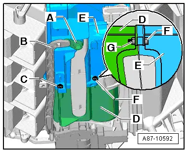
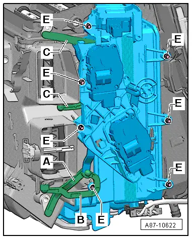
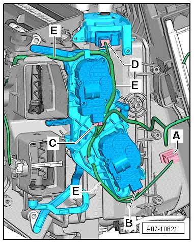
–  Lay the wiring -E- as shown in the attachment points at the mounting plate such that it cannot come into contact with moving components.
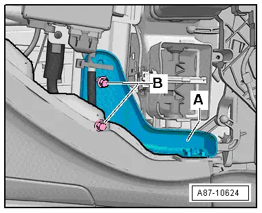
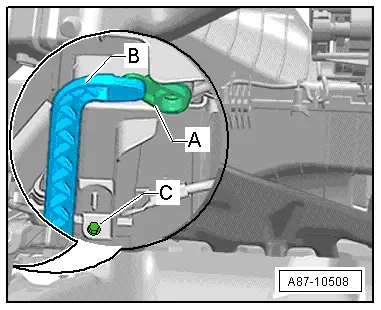
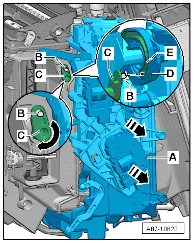
–  Plug in the connectors -B-, -C- and -D- at the control motors in line with the marks made.
–  Re-install all the other parts removed in reverse order.
–  Switch on the ignition.
–  Perform air conditioner basic setting and final control diagnosis → "Guided fault-finding" function of vehicle diagnostic, testing and information system VAS 5051.
  Note
t  The control motors on this vehicle are equipped with electronics. A new control motor only learns its position at the air conditioning unit in the course of basic setting and can then be actuated by the air conditioner operating and display unit, Climatronic control unit -J255- (all control motors are identical at present) → "Guided fault-finding" function of vehicle diagnostic, testing and information system VAS 5051.
t  During basic setting, control motor assignment and adaption are implemented on the basis of the arrangement in the series connection of the wiring. If the sequence is not as specified, the matching of the control motors and thus flap control will not be correct → Chapter (block diagram of air conditioner control motors).
–  Interrogate the event recorder of the air conditioner operating and display unit, Climatronic control unit -J255- and erase any faults displayed → "Guided fault-finding" function of vehicle diagnostic, testing and information system VAS 5051.
–  By making different settings on the air conditioner operating and display unit, Climatronic control unit -J255-, direct the air to the various vents and check whether the flow of air out of the vent actually changes in line with the setting.
  A87-10621

Removing and installing supplementary air heater elementZ35 / honeycomb element > < Removing and installing right heater housing (with right mounting plate for control motors detached)