| t
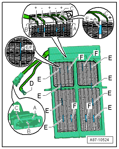
| The supplementary air heater element -Z35- is made up of several layers of resistor elements -E- and -F-. Given simultaneous actuation via all 3 inputs -A- to -C-, these can attain a joint heat output of approx. 1000 W. These resistor elements have a positive temperature coefficient (the resistance increases with temperature and the current input and thus the heat output decrease). |
| t
| The resistor-type heater elements (-E- and -F-) are actuated by way of the wires -A- to -C-. The current is discharged via the earth connection -D-. |
| t
| The design of the supplementary air heater element -Z35- is such that a current greater than 35 A cannot flow via any of the contacts -A- to -C- on switch-on. Immediately after switch-on, the resistance of the resistor-type heater elements -E- and -F- increases and the current decreases. |
| t
| To attain the maximum heat output of approx. 1000 W (3 x 333 W), the temperature of the resistor-type heater elements must be low and sufficient current must be supplied by the alternator -C-. |
| t
| The resistance of the heater elements is governed by temperature and is between approx. 0.2 and 5 Ω, measured between connections -A-, -B- and -C- (in the connector) and the earth connection -D-. |

Note | t
| For measuring the resistances and checking actuation of the supplementary air heater element -Z35-, unplug the connector at the air conditioning unit → Chapter. |
| t
| As resistances of less than 10 ohms cannot be measured with sufficient accuracy using workshop equipment, it is not possible to establish a short circuit in the supplementary air heater element -Z35-. |
| t
| The engine control unit / supplementary air heater control unit -J604- actuate the supplementary air heater element -Z35- in 3 stages. Fot this purpose, contacts -A-, -B- and -C- are supplied with voltage as follows. The corresponding wiring can be seen from the appropriate current flow diagram → Current flow diagrams, Electrical fault finding and Fitting locations. |
| –
| For stage „1“, voltage is switched by the low heat output relay -J359- to contact -A-. |
| –
| For stage „2“, stage „1“ is deactivated and voltage switched via the high heat output relay -J360- to contacts -B- and -C-. |
Note | The corresponding engine control unit constantly monitors the capacity utilisation of the alternator -C-. If this remains below a certain limit, the next stage is switched in. Switching back a stage is effected if a specified limit is exceeded. |
| Cut-in criteria for actuation of electric supplementary heater |
Note | These cut-in criteria in the air conditioner operating and display unit (Climatronic control unit -J255-) must be satisfied for a request to be transmitted to the corresponding engine control unit. |
| –
| The following prerequisites must be met for the air conditioner operating and display unit, Climatronic control unit -J255- to transmit a request for supplementary heater activation to the engine control unit: |
| t
| Engine running for at least 8 seconds and engine speed higher than 500 rpm. |
| t
| Engine temperature less than 75 °C |
| t
| Calculated ambient temperature less than 8 °C. |
| t
| Electrical system voltage greater than 12.2 V and onboard supply control unit -J519- not transmitting any request preventing activation. |
| t
| No faults stored in air conditioner operating and display unit, Climatronic control unit -J255- |
| t
| No faults stored in engine control unit and capacity utilisation of alternator -C- less than 30 ...77 % (depending on engine speed) |
| t
| On the basis of the setting and the temperatures measured, the air conditioner operating and display unit, Climatronic control unit -J255- has calculated that additional heat output is required to attain the specified passenger compartment temperature |
| t
| The air conditioner operating and display unit, Climatronic control unit -J255- has calculated that more than 90 % of the air is being routed through the heat exchanger of the air conditioning unit |
Note | Shut-off criteria for actuation of electric supplementary heater |
Note | Deactivation takes place as soon as a cut-in criterion is no longer satisfied in the air conditioner operating and display unit, Climatronic control unit -J255- or in the corresponding engine control unit or if one of the shut-off criteria is detected. |
| –
| The air conditioner operating and display unit, Climatronic control unit -J255- cancels the request for activation of the electric supplementary heater if: |
| t
| One of the cut-in prerequisites is no longer satisfied. |
| t
| The calculated ambient temperature is greater than 11 °C. |
| t
| The capacity utilisation of the alternator -C- is greater than 95 %. |
| t
| The air conditioner operating and display unit, Climatronic control unit -J255- has calculated that less than 60 % of the air is being routed through the heat exchanger of the air conditioning unit (position of temperature flaps). |
|
|
|
